X-SLS Amateur Build

0 Members and 1 Guest are viewing this topic. Read 12420 times.

jonsk2514

X-SLS Amateur Build
« on: 1 Apr 2023, 09:07 pm »
I am back again with another speaker build.  This time it is to build a pair X-SLS speakers.  These will be the rear channel speakers of the home theater system I am assembling.  My front speakers are a pair of X-MTMs and the center channel is the X-CS, all of which were previous builds.  I have also built a pair of X-LS speakers that I gave my Daughter as a present… :D

For this builds I will be drawing heavily from my experience from my build of the X-MTMs
(https://www.audiocircle.com/index.php?topic=170542.0),

And from my build of the X-LS and X-CS speakers
(https://www.audiocircle.com/index.php?topic=174915.0)

As with those builds, I will air my mistakes (I do it right because I do it twice) as well as my successes.  I hope that this helps others who may be hesitant in making one of these build to see that they can do it and helps them to avoid the mistakes that I have made.

I have minimal tools, maybe a little more than what some may have but nothing that something else could be used in place of what I have and nothing that would be considered to be “professional”.  The basics are…

A Dewalt 20v router (I hate cords!)


Yup - this has made it through all of my builds.  The plunge base for this has been very useful.  For bits, my go to has been a 1/8” dia up cut spiral cutter, 3/8” and 1/2” radius cutters for edges, and a 1/4” up cut spiral flush edge trimmer.

An old Craftsman 12” table saw


An old Craftsman router table


Miter Saw


With that, let the games begin.  And the start is with a layout sketch and cut plan for the sheet of MDF.


It took several tries at this in order to be able to have the place I bought the MDF from cut it so I could handle it.  A full sheet of MDF is heavier than I can handle a lone and too large to make it into the basement.  That cut location is at the bottom of this sketch.

And so it begins…  :thumb:
Again   :eyebrows:

mlundy57

  • Industry Participant
  • Posts: 3579
Re: X-SLS Amateur Build
« Reply #1 on: 1 Apr 2023, 10:40 pm »
And again, and again, and again ..... Youo are well and truly hooked now. There's no going back  :icon_twisted: :icon_twisted: :lol:

jonsk2514

Re: X-SLS Amateur Build
« Reply #2 on: 2 Apr 2023, 12:25 pm »
And again, and again, and again ..... Youo are well and truly hooked now. There's no going back  :icon_twisted: :icon_twisted: :lol:

 :rotflmao:

So true!  Especially now that I have actually ordered the kit from Danny.  I am committed now (in more ways than one…. :no_speak:   :lol:) …

Hey - Anyone know if Danny has had thoughts of offering brass plates with “GR Research” and the model on them for us to added to our builds?  It would be a nice to be able to show their origin.

JCarney

  • Full Member
  • Posts: 1124
Re: X-SLS Amateur Build
« Reply #3 on: 2 Apr 2023, 12:51 pm »
Hey - Anyone know if Danny has had thoughts of offering brass plates with “GR Research” and the model on them for us to added to our builds?  It would be a nice to be able to show their origin.
[/quote]

One of the AC members came up with some GR emblems he was willing to either share the drawings, or make them up for someone at cost. I quickly looked, but did not find the thread I'm referring to in the GR circle. Maybe someone else has a better memory than mine.

JCarney

nlitworld

  • Full Member
  • Posts: 1994
  • Strange things are afoot at the Circle K
Re: X-SLS Amateur Build
« Reply #4 on: 2 Apr 2023, 01:02 pm »

Hey - Anyone know if Danny has had thoughts of offering brass plates with “GR Research” and the model on them for us to added to our builds?  It would be a nice to be able to show their origin.

Contact NXSTUDIO-DRUMMER on here. He made some up that looked super clean. I ended up painting my speakers, so I painted/silver leaf the design in. Nice little tip of the cap to the speaker designer.

Good luck with the build.

JCarney

  • Full Member
  • Posts: 1124
Re: X-SLS Amateur Build
« Reply #5 on: 2 Apr 2023, 01:10 pm »
I knew someone would remember, thanks nlitworld.

JCarney

jonsk2514

Re: X-SLS Amateur Build
« Reply #6 on: 2 Apr 2023, 01:22 pm »
Thanks!  I’ll look into it.

Danny Richie

Re: X-SLS Amateur Build
« Reply #7 on: 2 Apr 2023, 09:28 pm »
Hey - Anyone know if Danny has had thoughts of offering brass plates with “GR Research” and the model on them for us to added to our builds?  It would be a nice to be able to show their origin.


One of the AC members came up with some GR emblems he was willing to either share the drawings, or make them up for someone at cost. I quickly looked, but did not find the thread I'm referring to in the GR circle. Maybe someone else has a better memory than mine.

JCarney

We still have a few of the ones shown in this picture.


jonsk2514

Re: X-SLS Amateur Build
« Reply #8 on: 3 Apr 2023, 01:10 pm »
Danny - Thanks!

The cut plan I came up with has the sides, tops and bottoms coming from one section of MDF and the rest from the other section.  The sides and top/bottom pieces are such that length of the top/bottom pieces is the same as width of the sides.  That way the sides and top/bottom pieces can be made with one cut across the MDF and then a cut across each of those to separate the the top/bottom pieces from the sides.   Then cut the width of the top/bottom pieces.  Theoretically, this should mean that there will be no fitup differences between these for the front to back of the cabinets.

Sides and Top/Bottom pieces cut plan from one section of the MDF


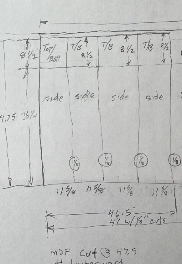
And, yes, the width of a MDF board is 49” not the 48” I have show…  :duh:

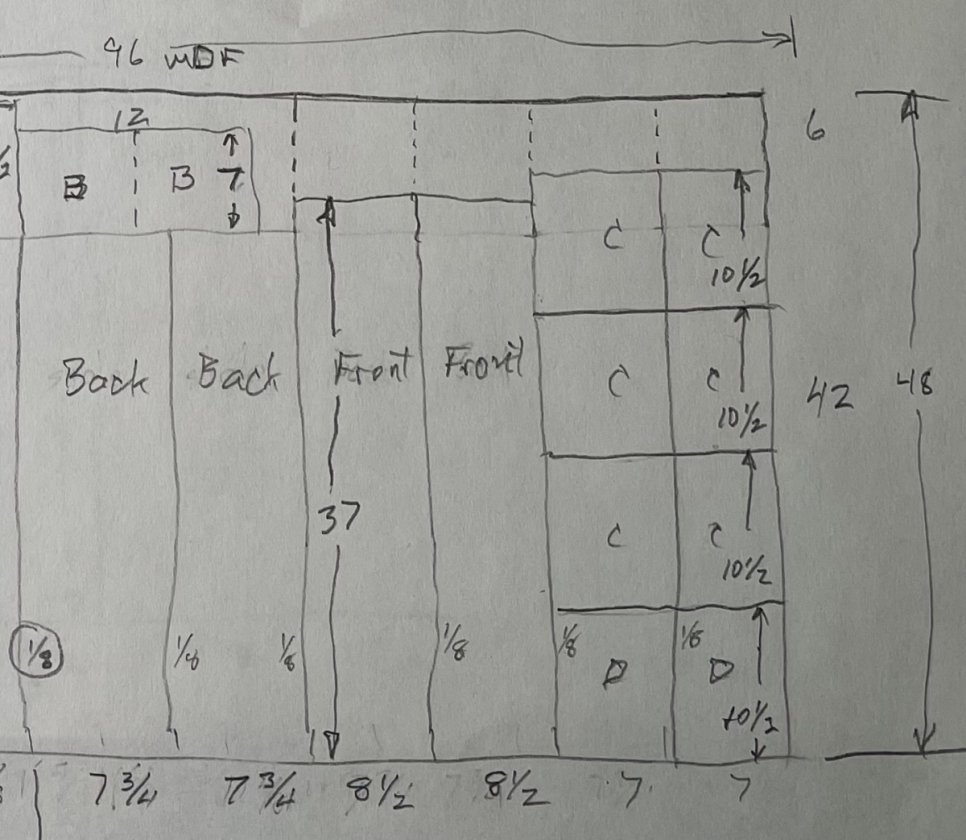
The reminding MDF piece cut plan for the fronts, backs, and braces


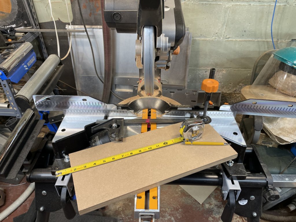
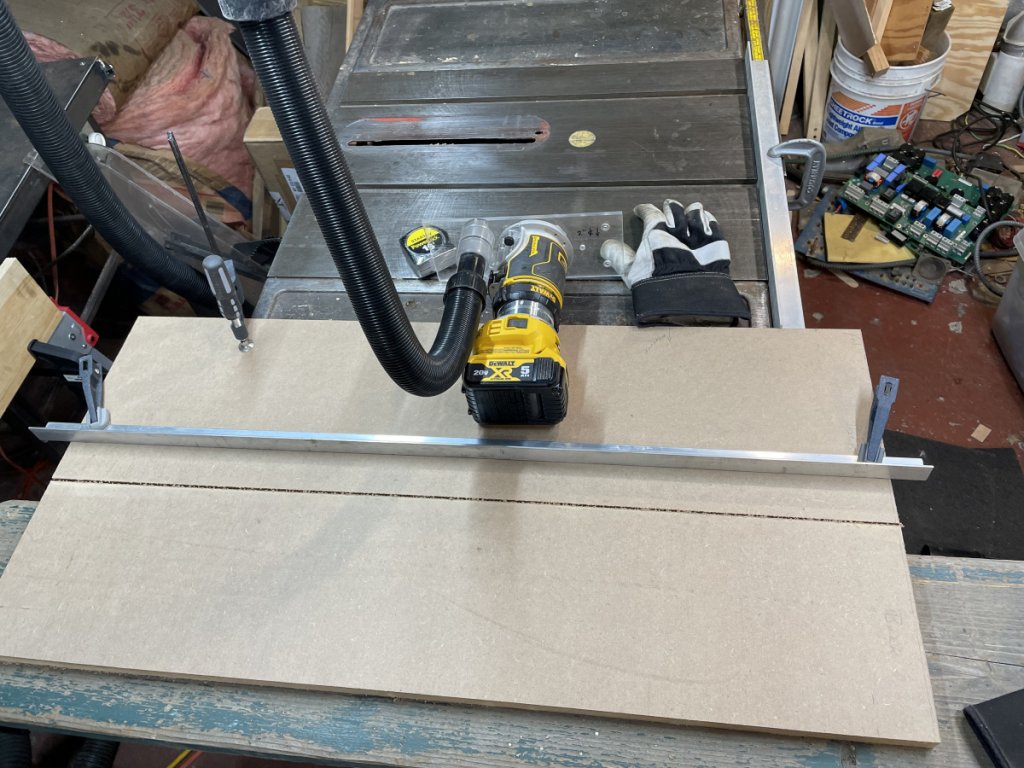
The one thing I did buy new for this project was a 6 foot long piece of 1x2 inch rectangular aluminum tube to use as an edge guide for cutting the MDF and to extend the fence on the table saw for trimming the longer pieces.

Most of the long cuts on the MDF were done with my router with the 1/8” up cut spiral cutter.


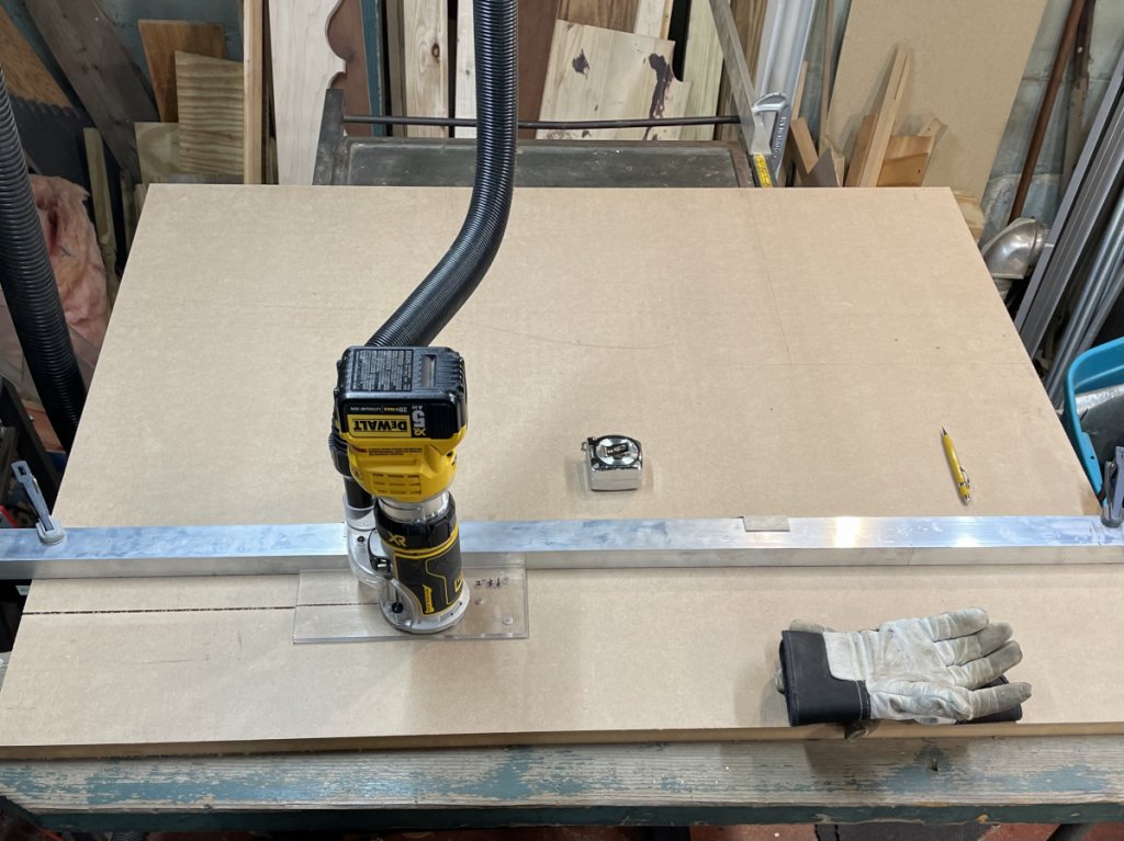
I used the router instead of just running it through the table saw as I feared that, with handling the board, any wobble would mess up the cut.  Even the approximately 4’x4’  piece of MDF is heavy for me and awkward to maneuver.  The router gives me good dust control, far better than using a circular saw or even the table saw.  This has all worked well in my previous builds.

And, yes, I wore a dust mask the whole time and had a fan running to blow air out of the basement.

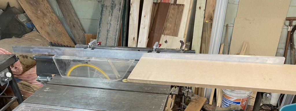
The table saw table and some stands with a 2x12 board made for a nice cutting platform and the space between the two allowed the end of the router bit to go fully through the MDF without hitting anything.  This setup worked better than making these cuts on the workbench where, in the previous builds, I had to prop everything up on boards to make clearance for clamps and the cutter.   

The final router cut…


Then the last cut was done on the table saw.


Note that all of the measurements for my router cuts were all made from the uncut edge of the MDF board.  That is, the edge that originally existed when the board was made.  In a way, that edge became a “datum” that didn’t change, making each successive cut would be square.  Had the measurements from a previously cut edge, then any errors, even very small errors (which will exist), would be compounded with each successive cut.

Once the length wise cuts were made, the miter saw made quick work of separating out the top/bottom pieces from the sides, each of the internal braces, setting the lengths of the fronts and backs…. Etc


jonsk2514

Re: X-SLS Amateur Build
« Reply #9 on: 6 Apr 2023, 07:15 pm »
  Got my GR Research CARE package today…


 :dance: :dance: :dance:

Now I can get going with cutting openings in the panels.

PS: nice job on packing and packaging all of this.  Even UPS was hardly able to put a dent in it…  :thumb:

jonsk2514

Re: X-SLS Amateur Build
« Reply #10 on: 6 Apr 2023, 08:24 pm »
Mistakes were made…  :duh:  :shake:  :bawl:

I should have read through my previous builds.  That is why they are up there; for me to have a record of my past work so I don’t have to reinvent the wheel or make past mistakes.

But did I do that?  Noooooo!   :oops:

I thought i remembered what I had done to route the edges of the panels and clearly my memory isn’t what it once was nor is my thought process.

I am at the point of routing the edges for the fitup rabbits on each of the panels.  This is a 2 step process on the router table and a cut on the table saw.


I have the router table setup with a length of 2”x2” aluminum tube with a cutout for the router bit and it makes for a longer fence.  This allows for better handling of the longer pieces.  The opening for the router bit is much smaller than that on the table itself which mitigates chances for the pieces to “step” when moving from one side of the bit to the other.  It is also set up with a spacer between it and the fence on the table, at each end, which allow for a quick change from a 3/8” cut to just under a 3/4” cut using a 3/4” dia router bit.  The finished rabbit cuts after being run through the table saw will be 3/8” deep and 3/4” inboard.

To facilitate this process, I marked the edges that were to be routed.  In this case, it is a top/bottom panel that will be routed on 3 edges.


Here is the first mistake I made….


The saw cut was made to establish the inboard edge of the rabbit, right at a 3/4” width and 3/8” depth

Problem was this weakened the MDF and the router operation caused sections of the MDF to be popped out.


The broken out piece is laying on top of the panel to the left of the routed area and the rough area can be seen where it came from.  In most cases this all cleaned up with a run through the router.  But on one panel, the popped out piece was on a corner and it went deeper than the router cut.  Fortunately this piece and defect will be on the bottom of the speaker and is in the back, so it won’t be seen.

The real problem with all of this was that when the piece would pop off, it would jar the router and that would change the height of the depth of cut…. And it would then cut too much.  :o

There is a saying… It is better to be lucky than good…

And I was lucky…

Fortunately the piece on which I found the router had shifted, I could use with a slightly deeper cut and all but the internal braces would fitup.  The shift of the router setting was minor, only 1/32” or so and the braces will require only a small trim to fit.

If I had read my past build (X-LS and X-CS) I would have known that the sequence for this routing process is to route first THEN make the table saw cut.

Again, fortunately, I caught this mistake before I had finished all of this routing and it went well on the remaining pieces.


JWCoffman

Re: X-SLS Amateur Build
« Reply #11 on: 8 Apr 2023, 01:08 am »
Cool!  I missed the start of this build but glad to see you start another.  May all your cuts be accurate...I guess I'm a little late for that, but I trust you will persevere.

jonsk2514

Re: X-SLS Amateur Build
« Reply #12 on: 9 Apr 2023, 05:14 pm »
Cool!  I missed the start of this build but glad to see you start another.  May all your cuts be accurate...I guess I'm a little late for that, but I trust you will persevere.

Thanks  :thumb:
Persevere I will but not without another mistake.. :duh:

Having gotten through all of the routing, I opted to do a dry fit up of the panels…


Jeeeezzzzzzzz  What did I do this time? :scratch:

The cut sheet (above) shows that the length of the top/bottom panels to be exactly the same as the width of the side panels.  So if that is true, then how did the this happen? :dunno:

Well I finally realized that I never measured the pieces that were to become the top/bottom panels.  What I didn’t realize was that, when they were cut from the sides, the remaining pieces would be over 12” long with a width of 11-5/8”, where the 11-5/8” dimension was the one I wanted to keep to match the width of the side panels.

In my haste, I didn’t measure and ASSUMED that the longer length was the one I wanted to keep (I blame the sketch I made for that really bad assumption as it “looked” like that is the way it would be), and I trimmed the other dimension to 8-1/2”.  So, I screwed up and lost the 11-5/8” dimension I had so carefully planned in…   :o :nono:

Well, as I noted before, it is better to be lucky than good.

And here I was lucky as the piece was too long and it was an easy, but time consuming, fix to trim the pieces.  Time consuming because they needed to trimmed to exactly the width of the side panels and the setup on the table saw took a while to get exactly right.

Ugh!

This looks much better and, on the plus side, all of the routing I did was perfect…


Hopefully my mistakes are behind me.

But I am a bit paranoid about the next step in all of this…

Glueing the panels together.  A mistake there will be really tough to recover from.  Plan is to glue these together the same as I did the X-CS speaker where I glued together the back, top, bottom, and one side.  Than the braces.

More to come.

KTS

Re: X-SLS Amateur Build
« Reply #13 on: 10 Apr 2023, 02:51 am »
Nice build, I wish I had your woodworking know how! I have only used flat packs and a lot of clamps! Looking forward to seeing your progress.

Kelly,

jonsk2514

Re: X-SLS Amateur Build
« Reply #14 on: 10 Apr 2023, 01:50 pm »
Nice build, I wish I had your woodworking know how! I have only used flat packs and a lot of clamps! Looking forward to seeing your progress.

Kelly,

Thanks  :thumb:

The flat packs are one of GR Research’s best ideas.  It is great these are available as they allow a whole host of people to enjoy Danny’s great designs and congratulations on your builds.  Hope you are enjoying them to their fullest.

As for clamps, there is more than one post with some variation of the remark - There are never too many clamps!  :lol:
« Last Edit: 10 Apr 2023, 03:27 pm by jonsk2514 »

KTS

Re: X-SLS Amateur Build
« Reply #15 on: 10 Apr 2023, 07:47 pm »


Don’t I know it!

jonsk2514

Re: X-SLS Amateur Build
« Reply #16 on: 11 Apr 2023, 01:41 pm »
Yup - That looks about right…  :thumb:

jonsk2514

Re: X-SLS Amateur Build
« Reply #17 on: 11 Apr 2023, 02:20 pm »
Glueing my X-SLS speakers together will be a process.  With the X-MTMs I built I found that, for me, glueing everything together in one sitting was not possible.  I also had a lot of discussion with others during that build as to how to install the braces.  What I did there was way overkill.  I also didn’t want to get into routing grooves in the panels as I was very doubtful that I could do it accurately enough to do the assembly.  That left glueing the braces in as butt joints.  This worked really well on my build of the X-CS.  But, as the saying goes - you don’t get something for nothing.  In this case I found the braces needed to be custom fit to each of the cabinets.  That was much more palatable to me than any of the other suggestions.  I also found a Titebond glue that was perfect for doing this job… Quick and Thick.  An attractive feature of this glue is that it fills small gaps.  This is ideal as, with a piece being butt joined to something on all 4 edges, there will surely be a gap somewhere.

To make this all work, gluing the cabinets together has become a 4 step process:
Glue the top, bottom and back to one of the sides.  This leaves the internals open for glueing the braces
Glue in the braces.
Glue on the other side.  This leave the internals open for installing the wiring, crossover and the NoRez.
Once satisfied with all of the above, glue on the front baffle.

And the first step in all of this is to mark up all of the panels.  This is where the cabinet parts all become “custom”, the speakers become somewhat unique and I label them as such…. “1” and “2” for lack of creativity.  And even though all of the panels start out without being unique top to bottom, this changes once the location of cutouts and the braces become defined.  Thus, all of these pieces get labeled “top” and “bottom”.  Still no creativity….  :lol:

Internals with layout lines for the internal braces:


This took only several hours because of my paranoid over checking resulting from my previous mistakes.  :o And guess what… I found a mistake.  This was caught before I progressed beyond just drawing lines and the reason I have one of these in my shop:


 :duh:

Let the glueing commence….

jonsk2514

Re: X-SLS Amateur Build
« Reply #18 on: 11 Apr 2023, 09:40 pm »
Step 1 - Create a half shell…

That is glue together the top, bottom back and one side.

With the errors I have made and glueing being a process with no recovery if errors are made, everything gets laid out in advance to the max extent possible.

At the bottom are lengthwise pipe clamps.  Love these thing.  The best I have found are the Bessey (hope I spelled that correctly), which I found at Home Depot.  I like that they have stand-off feet which makes them nice for this application where other clamps have to go under everything.


I lay out what I can before spreading glue on everything.


Because only the edges of the top and bottom pieces that will be against the side and the back will be glued at this time, I marked the area being glued with a pencil line


Look hard.  I know it is faint, but there is a line there.  I also laid out these pieces in the order they will be put in place.

I use the pipe clamp jaws to hold the top and bottom pieces at a slight angle which allows the back piece to be slipped in place.  This is what it looked like in the dry fit.


Glue spread on the joints.  The light yellow areas are where the glue is.


For this I use the Titebond original glue.  It has a medium fast setup time which allows for assembly of parts without rushing.

First the top and bottom pieces are located on the side panel, ensuring that the edges of all 3 piece are lined up at the front to ensue the front panel fits with no gaps.  Next the back panel is put in place on the glued edge on the side panel.  Then the front panel is slipped in place with no glue.  This allows the clamps around the glued side panel to be tightened.  With these loosely tightened, the other side panel is slipped into place and the remainder of the clamps put in place and tightened.  At this point all clamps are fully tightened.


I use strapping film to keep the front from being glued in place from a glue extruded from the joints being glued.


Doing it this way I am ensured that the unglued panels will fit after everything else is glued in place.  It could be argued that I could have done this with parallel clamps and right angle clamps, and not used the actual front and side panels.  However, knowing how I cut things, nothing will be exactly square and as result, if these are used, it is possible that the front and side panels may not fit as a result of the stack up of tolerances.  So, I figure why not glue everything together in the shape that they actually are…

jonsk2514

Re: X-SLS Amateur Build
« Reply #19 on: 16 Apr 2023, 08:49 pm »
Of course I cut the internal braces out when I cut/sized the panels.  They also have cutouts, which is a separate process.  This starts with making a template for making the cuts as the cutouts are oval.  I used some 3/8” pressboard that I had around.


This gets used with router bushings that work as guides in the template, which means that the template cutout is larger by the size of the bushing and then the diameter of the cutter, the 1/8” up cut spiral cutter in this case, is factored in.


I added framing to the underside of the template to retain the brace pieces.


Then a check of the template to the actual size of the cutout in the brace to ensure template, bushing and cutter will make the correct size opening.  It would be start over if not…  :roll:


Ready, set, cut…
I used the plunge attachment on the router and made 3 partial depth cuts to make the full cut.  This puts less stress on the router and bit.  Mostly I was worried about the small diameter bit being damaged by a single full depth cut.


And, yes, that is a grounding wire you see in the picture.  After making 5 speakers and wondering what would make the router momentarily kick off while using it on the MDF, it dawned on me that there was static electricity being built up somewhere (MDF dust in the vacuum hose?) and discharging.  Periodically I would get a small static shock and at about the same time the router motor would blip.  The grounding strap helped.  Go figure, that, without the 3 wire plug of a non-cordless router, static electricity would be an issue.  But makes sense that it could be.

The cutting template also served as a holder for rounding the cutout corners.  I know Danny’s drawings for the X-SLS speakers don’t specifically call for this, but it is called for his other speakers, and I seems like a good idea to cut down on internal reflection.  Hope I got that right, but that is my guess.


The “B” brace is a half brace that I made out of a single piece that has a hole cut in it and then the piece is cut in half through the center of the hole


« Last Edit: 17 Apr 2023, 12:33 am by jonsk2514 »