Upgraded NX-Otica crossover layout question.

0 Members and 1 Guest are viewing this topic. Read 721 times.

mlundy57

  • Industry Participant
  • Posts: 3577
Upgraded NX-Otica crossover layout question.
« on: 19 May 2022, 06:10 pm »
I'm in the process of laying out an NX-Otica crossover that has been upgraded with everything except the huge copper caps. I'm trying to keep the crossovers mounted to the base of the cabinets but space is very tight. Here is a picture of what I have come up with after a number of iterations. The vertical part that has the tube connectors is not shown. It will be attached to the end of the crossover board to maximize room for the components.

My main concern is the layout and orientation of the inductors. With this many inductors of this size in this small of a space I can't come up with a layout that has all the inductors positioned in opposing planes to every other inductor that is close to it.


Any ideas?

Thanks,

Mike

sledwards

Re: Upgraded NX-Otica crossover layout question.
« Reply #1 on: 19 May 2022, 09:33 pm »
Hey Mike:

Just curious, when I built my crossovers, Danny's design called four 4 coils. Where do the extra 2 you have placed come into play?

Steve

BGA

Re: Upgraded NX-Otica crossover layout question.
« Reply #2 on: 19 May 2022, 10:02 pm »
Hi Mike,

I built mine with the exact parts you have including the Path resistors, except I only had four foil inductors??  I eventually built the tweeter crossover on a separate board and installed it higher up on the cabinet, makes building the mid and woofer portion much easier.


Al

Jaytor

Re: Upgraded NX-Otica crossover layout question.
« Reply #3 on: 19 May 2022, 10:25 pm »
Here's what mine look like.


sledwards

Re: Upgraded NX-Otica crossover layout question.
« Reply #4 on: 19 May 2022, 10:56 pm »


So this my ‘as built’ configuration. Since then I have gone with Miflex bypass caps and Audionote resistors. But why do our builds contain different numbers of coils?

AKLegal

  • Full Member
  • Posts: 329
Re: Upgraded NX-Otica crossover layout question.
« Reply #5 on: 19 May 2022, 11:42 pm »
I'm thinking that a stray inductor slipped into the photo. :D

mlundy57

  • Industry Participant
  • Posts: 3577
Re: Upgraded NX-Otica crossover layout question.
« Reply #6 on: 20 May 2022, 03:04 am »
Yep, the inductor on the bottom right at the beginning of the tweeter circuit doesn't go there. It's for the second crossover. I knew something didn't look right. That's why I made the post.

Thanks all

Hobbsmeerkat

  • Industry Participant
  • Posts: 2542
Re: Upgraded NX-Otica crossover layout question.
« Reply #7 on: 20 May 2022, 03:57 am »


So this my ‘as built’ configuration. Since then I have gone with Miflex bypass caps and Audionote resistors. But why do our builds contain different numbers of coils?

Looks like an NX-Treme crossover maybe? They're quite similar, but the Otica has a notch filter in the tweeter circuit making it have one more than the NX treme.

E-Zee

  • Industry Participant
  • Posts: 149
    • Diy speaker resources and crossover assembly services
Re: Upgraded NX-Otica crossover layout question.
« Reply #8 on: 20 May 2022, 08:28 pm »


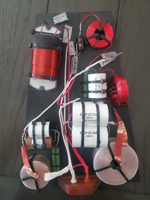
It is a complicated layout.  5 inductors on one board is a lot.

I am a fan of using multiple boards when needed. In this case, my preference would be to remove the large iron core inductor from the board and mount it just above or below one of the lower horizontal supports.  It could be mounted to the support itself or to the side wall.  With that iron core removed you have a little more space for the remaining inductors and components.

With this many inductors on board, the least amount of harm is done by laying down additional inductors.   
There is sufficient published testing data to support this, but  since that's not the topic of this discussion I wont go too far into the weeds on it.  Basically,  the drift of value from two laying down inductors, even if only 3 inches apart, with magnetic fields pointing upwards and parallel, is completely insignificant and less than manufacturer variance from part to part.  The potential drift of value from standing inductors oriented with magnetic fields intersecting can easily be greater.  If you are forced into possible conflict by too many inductors in a tight space,  than laying down additional inductors is the safest option.

In my photo above, you will see that 3 of the 4 coils are laying down in the corners, as far from each other as possible.  The only potential conflict there, but still minimal, is between the iron-core and the standing inductor.  If that iron-core was removed to a different location, there would be no potential negative interactions. 

Elon
Elon@ezeescrossovers.com
« Last Edit: 20 May 2022, 09:56 pm by E-Zee »