LGK 2.0 TL design

0 Members and 1 Guest are viewing this topic. Read 2291 times.

Martin Garrish

  • Jr. Member
  • Posts: 15
LGK 2.0 TL design
« on: 12 Nov 2022, 02:15 pm »
As discussed in the YouTube channel comments, I have found time to draft a transmission line design for the LGK 2.0 full range driver. To do this I developed a process using Excel for the packaging and David McBean's HornResp software for the analysis. To give an idea about how much effort went in, the iterations were as follows:
0. Use LGK 2.0 reflex as starting point.
1. Front port vertical folded TL (as PMC ATL designs).
2. Front port horizontal folded TL.
3. Front port reflex (lower tuning).
4. Rear port folded tapered TL (as Martin King designs).
5. Rear port vertical baffle TL.
6. Final reflex transmission line RTL hybrid.

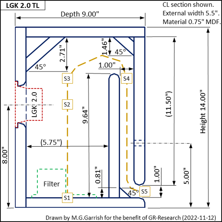
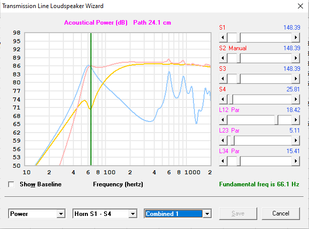
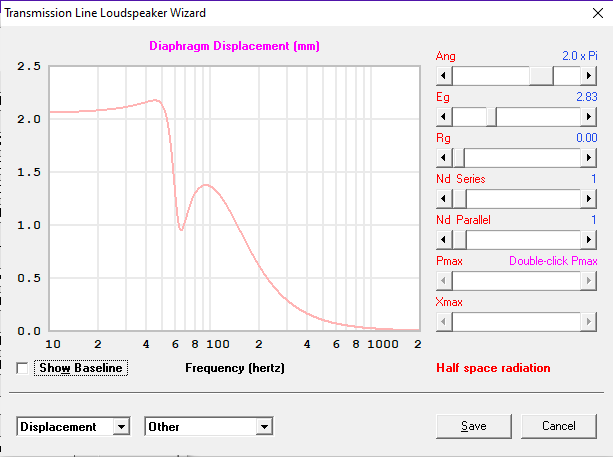
So, the model I built for the existing LGK 2.0 showed a cabinet mode of 78Hz, with some minor midrange modes. I wanted to improve the power handling below this, so decided to tease out the 1/4 wave mode to 66Hz (0.25 octave lower). Do I recall correctly that the latest LGK 2.0 drivers can handle 2mm xmax? The switch from front port to rear port was because I found that the extra time delay helped with some midrange phase cancellations from the TL output. The 3/4 wave mode is cancelled by careful driver positioning, and the 5/4 wave mode is cancelled by putting the vertical baffle 1/4 wave behind the driver at this frequency. Hornresp overpredicts modes above this as the 1D horn assumption no longer applies. The real advantage of transmission line over reflex is that you can critically damp the 1/4 wave mode to tease out the bass without too lumpy a response before roll-off (I was aiming for a 1.5dB corridor with gentle LF roll-off). The corner pieces and radiused edges are just there to improve the aerodynamics and to make sure that no unwanted reflex modes sneak in.

I am having to watch my pennies at the moment, but want to share what I came up with. The rough draft CL section drawing shows that the design was done in inches as I noticed the original was designed in inches. I have omitted features, like driver and tube connector machining, as those will be a straight copy from the existing LGK 2.0 design. I put dimensions to 2 decimal places, but they are not that critical. I imagine Killian will want to play with the design to suit manufacture for completed cabinets and/or kits. For BSC filter fitment I suggest putting the trap door in the base of the cabinet as there is no access from the rear. Drilling holes in the baffle for speaker cables is fine - just seal them. For the stuffing start with with 26g (~1 ounce) of acrylic fibre then adjust for smoothest base - evenly distributed right up to the location marked "S4" on the draft CL section drawing. Transmission lines are not too finicky about stuffing, which is why they are so suited to the DIY market. Please feel free to ask questions about the design process.

Danny, if you do like the LGK 2.0 TL design then I'm happy for you to offer it on your website. There does seem to be a strong audiophile following for full range transmission line speakers, and I'm pretty sure you're going to like how these sound. It would be nice if you could throw the prototypes my way if they do get tested - I'm partial to walnut veneer.  :wink:


Best regards,

Mart

Martin Garrish
B.Eng, B.Sc, M.Sc.


« Last Edit: 13 Nov 2022, 01:40 pm by Martin Garrish »

Danny Richie

Re: LGK 2.0 TL design
« Reply #1 on: 12 Nov 2022, 06:27 pm »
I would recommend the same thing we go through with any model we work on. You've done a good job in the design stages. So if you want, build one, send it to us, and we will test it, measure it, and give you feedback on it. If it work well then we can give it a thumbs up, and offer the plans with all credit to you for the design.

Martin Garrish

  • Jr. Member
  • Posts: 15
Re: LGK 2.0 TL design
« Reply #2 on: 13 Nov 2022, 12:50 pm »
Thanks, Danny. It is a generous offer.

I'll come clean about my reason for using the LGK 2.0 driver as a guinea pig for transmission line development: I've pulled together enough magnet system parts to build a second pair of these 8" FR bad boys (with good in room dispersion). The photo is acoustic suspension, but I'm really set on version 2 being TL to get to deep base. I never got the BL high enough because I would have to find someone that can edge wind aluminium voice coils. So it made sense to find an FR with similar design philosophy, but lower Qes, that I could use to benchmark various TL designs - the LGK 2.0 driver was the obvious choice.


The sound accuracy of these is that you are in the same room as the musicians (it can actually feel uncomfortable at times). The TL cab version will be birch plywood matrix construction with similar damping methods to top end ATC cabs. Preliminary calculations show <30Hz with plenty of headroom. I'm toying with the idea of active feedforward transient correction to make them true monsters of the deep. I really do have to save my pennies!

Music link (this is one of my benchmarks for TL design  :icon_lol: )
https://www.youtube.com/c/RogerSayerOrganist
« Last Edit: 13 Nov 2022, 05:02 pm by Martin Garrish »

Martin Garrish

  • Jr. Member
  • Posts: 15
Re: LGK 2.0 TL design
« Reply #3 on: 19 Nov 2022, 07:30 pm »
Update on LGK 2.0 TL project: I've managed to package the same response as the TL above in a speaker that is almost identical to existing LGK 2.0 reflex speaker footprint. It is 3" taller, but you get an extra 1/4 octave bass for that along with improved power handling. The port is as small as I dare go, while keeping velocity below 10m/s at maximum power. The smaller cabinet means that the driver will damp TL more. So stuffing density up to port entrance will be reduced from above, with Hornresp showing 18g acrylic fibre fill as the starting point. As Danny has constructively commented this risks allowing some HF cabinet modes to remain undamped. I have used the same tricks as above with driver positioning to avoid 3/4 wave mode and TL depth to avoid 5/4 wave mode. To be sure about no HF leakage I recommend increasing the stuffing density above the BSC filter to just below the driver. This appears to have almost no influence on the 1/4 wave mode but will help absorb HF. Again BSC filter will need a trap door in the base of the cabinet.

Problem now is logistics, as I'm based in the UK so making the speaker pair then shipping them to US seems counter intuitive. I'm waiting for a rough estimate on the above design from Killian, so that will help me to decide next actions...

Mart


Analysis done in metrical, but designed in steam units to assist manufacture.


Flare at location "S5" input into Hornresp with constant port area and a small length correction.


This is at 1W input power.


This is at maximum power (assuming the new LGK 2.0 xmax of 2mm).

« Last Edit: 20 Nov 2022, 04:01 pm by Martin Garrish »

planet10

  • Industry Participant
  • Posts: 1918
  • Frugal-phile (tm)
    • planet10-hifi
Re: LGK 2.0 TL design
« Reply #4 on: 19 Nov 2022, 07:44 pm »


A BR with a high aspect ratio vent that adds R to the vent. If you got the alignment right you have just designed a miniOnken for this little FR.

A proper TL will more bass potential.

dave

Martin Garrish

  • Jr. Member
  • Posts: 15
Re: LGK 2.0 TL design
« Reply #5 on: 19 Nov 2022, 08:14 pm »
Dave, are these the designs you mean?
https://www.planet10-hifi.com/fonken.html

What I'm trying to do with the LGK 2.0 TL is to keep the design comparable with existing reflex design in terms of size and cost but reduce driver excursion below existing port frequency. I tried many variations, including proper TLs, before reaching the design iteration presented above. This included extending bass reinforcement down to 56Hz, one full octave below driver Fs. However, by only considering 0.75 octaves below driver Fs then the frequency response stays within a 1.5dB corridor. For 56Hz alignment you have to accept a 3dB corridor, which would sound boomy.

I think of TLs as combining the benefits of acoustic suspension rear wave absorption with an extension of reflex bass reinforcement (from speed of sound). As you suggest, a larger cabinet does work better for low-Q resonance but then it's not comparable with existing design. See above.

Mart

planet10

  • Industry Participant
  • Posts: 1918
  • Frugal-phile (tm)
    • planet10-hifi
Re: LGK 2.0 TL design
« Reply #6 on: 19 Nov 2022, 08:51 pm »
That is the original… since then we have done literally 100s of miniOnkens designs for a wide swatch of drivers.

It is a specific alignment that uses the highR vents to create a box pushed towards aperiodic that is more tolerant of changes in T/S due to dynamics (or how high the wick is turned), they have very elegant, detailed, articulate bass, but they only go as low as they go, and typically a smaller enclosure.

Your impedance curve is very similar to that of the original FonkenPrime.


There is more history here: https://www.diyaudio.com/community/threads/fonken-style-box-nomenclature-what-is-with-those-names.160747/'

The classic boxes have the vents running down the sides, but the Classic Golden Ratio and more specifically the Compact Floorstander, have the same shape as yours, but stretched out to be a floorstander.


I might get in some triuble posting this link, it will give you an idea of how widely applicable this alignment is: https://www.diyaudio.com/community/threads/planet10-hifi-minionken-plan-set-subscriptions.186350/page-8#post-7034792

Quote
What I'm trying to do with the LGK 2.0 TL is to keep the design comparable with existing reflex design in terms of size and cost but reduce driver excursion below existing port frequency.

The ultimate expression of that would be an aperiodic box. The highR vent pushes a BR in that direction.

dave


Martin Garrish

  • Jr. Member
  • Posts: 15
Re: LGK 2.0 TL design
« Reply #7 on: 19 Nov 2022, 09:29 pm »
Thanks, Dave. This is good info, although first link was not found (don't worry).

You're about right with the comments on aperiodic tuning of the LGK 2.0 TL. The LGK 2.0 is one of the few high quality FR drivers made out of paper, which is what appealed to me. Paper is easy to damp with silicon fluid. I even damp spiders to get out every last eigenmode! It just suffers a little from limited area and excursion.

I'm not generally impressed with the other selection of FR drivers on the market. The Jordan JX92 design used stiff aluminium foil laminated to front and back of a plastic diaphragm to make what would normally be a flexural wave become a shear wave. In theory, this should have meant good HF dispersion as shear waves are frequency independent while flexural waves are frequency dispersive (speed proportional to sqrt(frequency) from memory). However, the high inductance lead to HF roll-off so even this FR driver was optimised to beam HF more than ideal. Also, as the Eikona modifications show this diaphragm is not easy to damp. Paper just works...

Actually, I think GR has run into the same FR problems I did a few years ago. To get good excursion you have to switch to longer solonoid edge would aluminium voice coils and accept a larger magnetic gap. With NdFeB magnets this doesn't present such a big challenge as you can use push-pull magnets like on the M165 woofer. Then the challenge is to keep the BL high and the inductance low...

Mart

planet10

  • Industry Participant
  • Posts: 1918
  • Frugal-phile (tm)
    • planet10-hifi
Re: LGK 2.0 TL design
« Reply #8 on: 19 Nov 2022, 11:50 pm »
I have heard a lot of FRs.

I could not live with the Jordans, 3 sets of JX92, 1 of Eikona. To a lessor extent the J6T, which is also the original Mark Audio Alpair 5, along with 1st gen A6, A10, had similar issues. With the second generation, particualrily the Alpair 7, Mark kicked his Jordan apprenticeship, and did some of his own things. The next gen A7.3 was better in this respect, as are most of the current drivers.

Most of the Alpairs are very good. Only one paper cone at the moment (A10p). There is a CHP-70.2, it is good but has a top 2 octaves shelved down.

There are some other drivers i find OK, most need some tweaking.  Fostex FF85wk worthy of mention. There are some nice vintage drivers, but tend to be rare and of variable quality and aging.

I have also been tweaking drivers since the late 70s, and this culminated in EnABL. Sadly no more. Most drivers have other pre-EnABL tweaks.


dave

Martin Garrish

  • Jr. Member
  • Posts: 15
Re: LGK 2.0 TL design
« Reply #9 on: 20 Nov 2022, 10:09 am »
Thanks for the excellent information, Dave. This is Danny's GR-Research forum so I'll hold off talking too much about other drivers here.

My motive is only to help GR-Research develop the best full range product it can. I made the switch to full range drivers long ago, and once you've been spoiled with that exact 3D soundstage you just never want to go back to separate tweeters. I do look at co-axial designs from time to time, although neither KEF or SEAS use flexible paper cones. Keeping the voice coil light with low inductance, while meeting high BL with good linear excursion is a challenge for a well designed FR. If GR is entering the FR world then the least I can do is to drop the odd hint to help Danny improve the product. We all win there.  :)

In fact, your "proper TL" comment actually gets to the heart of what I am trying to do with the LGK 2.0 TL project. By choosing a suitable guinea pig driver I have been able to use David McBean's excellent HornResp software to understand the design rules of transmission line speakers and see where those rules lead. The conclusion I have reached is that both TL and BR designs are part of the same family of resonant bass extension. However, BR software alone can not account for the subtleties of using the speed of sound in TL design. My starting point was a front ported tapered "proper" TL but as the iterations progressed what I ended up with was a rear ported reflex transmission line (RTL). So the design has features that make it look like a BR and a TL because it hopefully pulls the best from both worlds. With an active filter you could go from 0.75 octave to full octave bass extension. So, I mean what I say about offering the LGK 2.0 TL design to GR-Research so that we all win.

I read the white paper on EnABL, so wanted to check my understanding. The EnABL process is adhering stiff membranes onto flexible surfaces, like cones and baffles, to diffuse the flexural wave by providing half wave cancellation as the wave passes through. So it is effectively providing termination impedance in a manner similar to a 1/4 wave TL stub for absorbing a particular frequency. Is that a fair summary? How does it compare to soaking paper cones in silicon fluid to absorb the flexural wave? I really have found nothing that sounds better, especially if you treat the spiders too. In fact before I found silicon fluid I actually did write off some FR drivers by soaking them in honey and golden syrup! It works for about 24 hours then the honey dries up.  :duh:

Mart
« Last Edit: 20 Nov 2022, 04:37 pm by Martin Garrish »

Martin Garrish

  • Jr. Member
  • Posts: 15
Re: LGK 2.0 TL design
« Reply #10 on: 20 Nov 2022, 12:34 pm »
Definitely not saying this is a good idea, but this is what happens if you overextend that bass to get the full octave from LGK 2.0 driver Fs 113Hz. Quick look see only so ignore dimensions, and I would normally do a few iterations for least worst alignment. You could pull that flat with an active filter, or just get a bigger driver! Also the stuffing density is getting a little low, so it's going to be difficult to stop noise leaking out of the cabinet...


planet10

  • Industry Participant
  • Posts: 1918
  • Frugal-phile (tm)
    • planet10-hifi
Re: LGK 2.0 TL design
« Reply #11 on: 20 Nov 2022, 05:28 pm »
I have reached is that both TL and BR designs are part of the same family of resonant bass extension. However, BR software alone can not account for the subtleties of using the speed of sound in TL design.

As one dimension of a BR box starts to become considerably longer than the others the box transitions into a TL. You can, and we have, designed boxes that are hybrid. This complilation of Martin King’s simulation results shows what happens (the Voigt is a TL).


The start & end xsection, the length, driver offset, terminus offset, any mass-loading, coupled with the T/S parameters are the primary determinants of a TL.

Quote
the speed of sound in TL design

This old-school misinformation has been shown to be false. The changes in the speed of sound thru any damping are inconsequential. This piece of misinformation camr from not understanding how the shape (taper) of the line affects things.

Quote
(RTL). So the design has features that make it look like a BR and a TL because it hopefully pulls the best from both worlds. With an active filter you could go from 0.75 octave to full octave bass extension.


It only matters in terms of room loading, or potential vent resonances whether the terminus is on the back or the front (side or bottom). The RTL (term has been used before), us a nacient Daline.

Quote
The EnABL process is adhering stiff membranes onto flexible surfaces, like cones and baffles, to diffuse the flexural wave by providing half wave cancellation as the wave passes through.

Nothing really adds stiffness, and it is still anyone’s guess as to how or why it works. We did discover, with gen 2 EnABL, that the rings fall right on top of where the transition from one defining curve to the next (this by talking with the designer, and the cone being made from a number of curves blended together into the cone shape),

Quote
especially if you treat the spiders too.

You should maybe try one of the new drivers that have no spider.

Quote
With an active filter you could go from 0.75 octave to full octave bass extension

You have to be VERY careful trying to extend the bass of any box with a hole in it as the driver unloads below the tuning any you ar eboosting the output below that tuning frequency, greatly increasing excursion, distortion, less loudness and potential damage to the driver. EQing more bas sis best left to sealed boxes.

dave

planet10

  • Industry Participant
  • Posts: 1918
  • Frugal-phile (tm)
    • planet10-hifi
Re: LGK 2.0 TL design
« Reply #12 on: 20 Nov 2022, 05:33 pm »


Do note that the deflectors do nothing but decrease the box volume, and provide a tiny bit of bracing. They could easily be lost.

dave

Martin Garrish

  • Jr. Member
  • Posts: 15
Re: LGK 2.0 TL design
« Reply #13 on: 21 Nov 2022, 11:39 am »
Some good information there, Dave.

Using Ansys multi-physics on this project would take up a little too much time! I'm confident David McBean spends many hours thinking about how to improve Hornresp. I should join your diyAudio forum to learn a little more from his thread!

The rear port came about as I found that there actually needs to be a time delay to stop TL output cancelling driver output at 800Hz. It was a thread on your forum that taught me that trick. In reality this may be an artefact of a 1D calculation to a 3D problem, but it also packages better.

You are quite right about the deflectors though. They are really there to give me confidence that the 1D Hornresp software will produce credible results for a 3D problem (they also help avoid aerodynamic flow boundary layer separation at the line corners too). When looking at Danny's original design I put in a "horn element" that had ~0 length. Hornresp can do 0D bass reflex calculations, but my objective was to understand the 1D design rules for TL. Actually, I like the idea that the final design will probably be very similar to the original GR-Research offering, but with the port repositioned and overall cabinet repackaged to optimise 1/4 wave and cancel 3/4 & 5/4 waves. Convergent ideas tend to be the right solution to a problem...

I've never been that convinced about rear horns like the Voigt. In theory, the horn loading should provide more bass reinforcement, but they always seem to produce a lot of cabinet noise. I like Danny's analogy of it's like someone shining a flashlight in your eyes as you listen. I just can't get past the cabinet noise to enjoy the horn loaded bass. I played a little in Hornresp, admittedly without a decoupling chamber, but couldn't convince myself it would work.

Mart


Quick & dirty attempt at MLTQWT for LGK 2.0 driver. There doesn't seem to be any advantage over CTL design...


« Last Edit: 9 Dec 2022, 12:22 pm by Martin Garrish »

planet10

  • Industry Participant
  • Posts: 1918
  • Frugal-phile (tm)
    • planet10-hifi
Re: LGK 2.0 TL design
« Reply #14 on: 21 Nov 2022, 05:15 pm »
Quote
TL output cancelling driver output at 800Hz

An artifact from the length of the vent? You should be able to damp that out, but it is a reason to put the vent on the back.

Quote
(they also help avoid aerodynamic flow boundary layer separation at the line corners too)

At the frequencies involved they will not.

Quote
I've never been that convinced about rear horns like the Voight.

Voigt, there is no “h”. It has been shown that a voigt needs to be mass-loaded to tame the ripple. There is a direct relationship between an ML-Voigt and an ML-TL. And the BIB (which uses a corner of the room for mass loading) can produce serious results.

dave

dave

Martin Garrish

  • Jr. Member
  • Posts: 15
Re: LGK 2.0 TL design
« Reply #15 on: 21 Nov 2022, 08:57 pm »
Good spot, Dave. Typo in "Voigt" corrected above.

To simulate a front port, this is Hornresp output with no port output delay (in red) with original left in for comparison (in grey). This is really an artefact of 1D code assuming uniform excitation of the line cross section. Truthfully, the driver will decouple above the 1/4 wave cross section depth of the line, because it is off to one side. But rear port seemed a sensible fix and actually packages better.


Mart

Danny Richie

Re: LGK 2.0 TL design
« Reply #16 on: 21 Nov 2022, 11:01 pm »
We tested the EnABL'ed process on some of our M-130 woofers. They were sent to us completely done.

We were not about to find any measurable or audible differences in anyway.

I also would not recommend trying things like that on the LGK cone. There is no telling what the result might be if there is any difference at all. The lightly painted dots really doesn't do anything, but a heavier doping on the cone will alter the response and output level.

Coming up with ways to extend the lower end is fun to do. However a really easy solution to increase bottom end and power handling is to build the LGK 2-.1 model with the 5 inch woofer under the LGK driver.

https://gr-research.com/product/lgk-2-1-kit-pair-2/

https://www.youtube.com/watch?v=aWDPieaILIg&t=1044s  Check out the audio clips on this one.

And a follow up: https://www.youtube.com/watch?v=8w4MTWYSIW8&t=56s

planet10

  • Industry Participant
  • Posts: 1918
  • Frugal-phile (tm)
    • planet10-hifi
Re: LGK 2.0 TL design
« Reply #17 on: 22 Nov 2022, 01:16 am »
Quote
EnABL'ed process on some of our M-130 woofers

Do you have a picture Danny.

I do have some measurements that show difference, bu tAFAIC it is open to interpretation.

I strongly sispect that what you measured is not what EnABL does.

dave

Martin Garrish

  • Jr. Member
  • Posts: 15
Re: LGK 2.0 TL design
« Reply #18 on: 22 Nov 2022, 12:06 pm »
I also would not recommend trying things like that on the LGK cone. There is no telling what the result might be if there is any difference at all. ...a heavier doping on the cone will alter the response and output level.

Danny, my experience with silicone fluid soaking paper cones is that much of it eventually drains back out so it has no noticeable effect on T-S parameters other than a drop in Qms if you treat the spider. The cone stiffness and density will be the same so same on/off axis response, just a lot smoother. Back in the day I did loads of testing with Liberty Audiosuite and was impressed with the result. But, as you say, don't take my word for it just try it and and listen for the difference...

Coming up with ways to extend the lower end is fun to do. However a really easy solution to increase bottom end and power handling is to build the LGK 2-.1 model with the 5 inch woofer under the LGK driver.

You are quite right, it is the simplest solution but no T-S parameters for the 5" woofer are available. My objective was to investigate small TL design so the exercise was done around LGK 2.0. But, the general design could easily be adapted to any low Qts 2 way system for a free 0.25 octaves of bass. You'd need subjective tests on whether it kept cabinet noise down.

Those audio clips sounded very good on my 8" FRs - and believe me not many speaker recordings do.
« Last Edit: 22 Nov 2022, 10:03 pm by Martin Garrish »

planet10

  • Industry Participant
  • Posts: 1918
  • Frugal-phile (tm)
    • planet10-hifi
Re: LGK 2.0 TL design
« Reply #19 on: 22 Nov 2022, 04:15 pm »
Of course Danny would say that.

I have been modding drivers for over 40 years, i am pretty good.

dave