Well, I’ve come to the end of my RP-600M upgrade! On to the 504C! Then I’m going to pull apart the SPL-120 and re-work that.
For now, some photos! I think the kits should be in stock very soon, and should be shipping for those waiting. I hope! Or maybe I’m the last one to do this, late to the ball game as per-usual.
Anyways... Somethings I found.
1. Heat shrink.. maybe I did not get enough, but I pulled out some from my own stash. Not a big deal!
2. Board length. Make sure your not exceeding 6 to 6.5 inches.
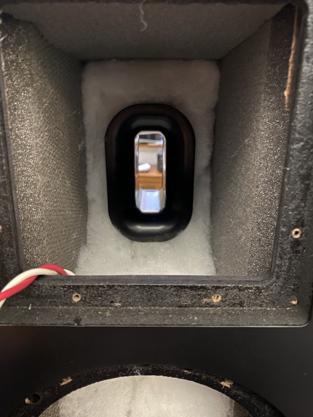
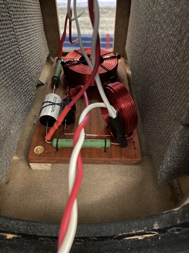
3. Tube connector location. I feel it’s better to pick the higher location in the binding post cup! I went lower, it works, but is tight with longer network board. 7/16th on a mult-bit (stepped bit) is perfect! I did not use hot glue! That can let go and be messy! I used a very good 2 part epoxy. Still, hot glue or not I suggest to sand or scuff-up the area you plan to glue! IE the tube connector plastic area, and the plate they are mounted to! Wipe plastic off after.
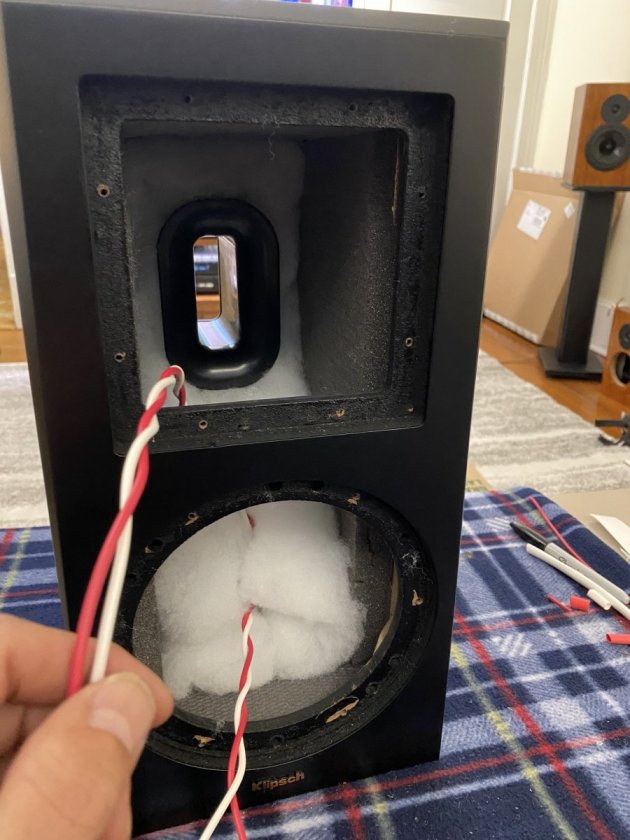
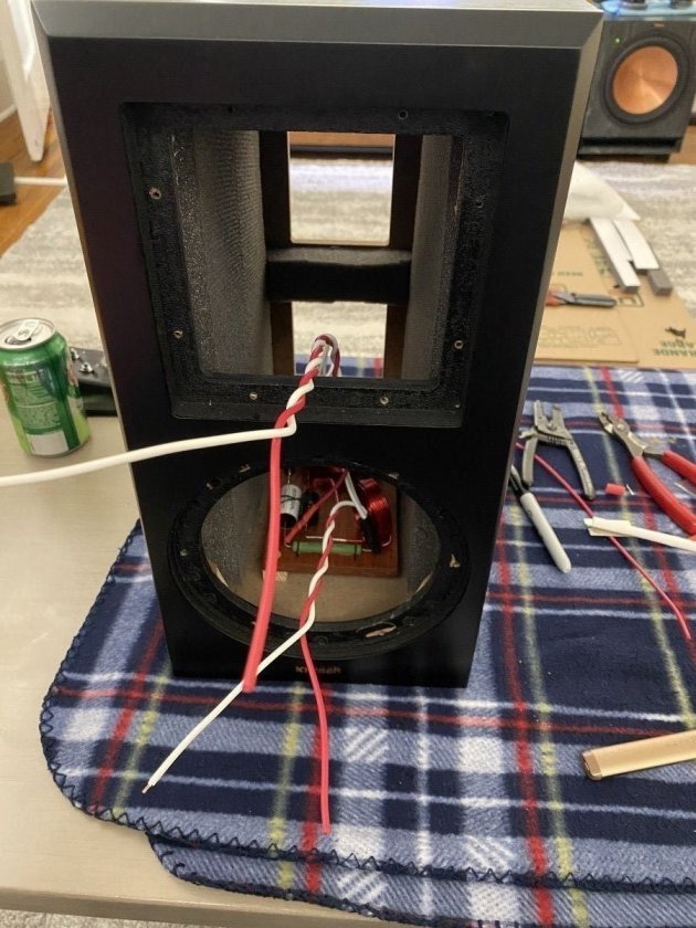
4. To gain some extra room, cut the black posts off the binding cup where the stock xover was mounted to! Those four posts can be cut down! This will allow less interference when installing! More so if you’ve added no res to the bottom of cabinet in front and behind the network board. Just makes things clean and nice. Just make sure your cuts don’t end up flying through the air, back into the box!! (Was a crazy shot tho! Lucky for me it was sitting on the no res I added behind the binding plate.
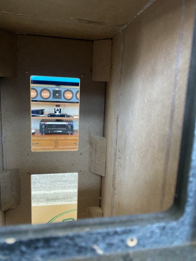
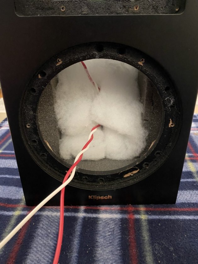
5. Before adding the no res, cut all your no res! I used Homers cut sheet, with a modification to it (swapped location on sheet to get a larger extra piece) this cut sheet was awesome! Thanks again! If you don’t have a table saw, get your self a flexible hand saw for flush cutting! I used this saw going in one direction.. it provided very flat and nice cuts! Wipe your walls down before applying! Harbor Freight for the saw, I’m add a photo.
6. If you don’t have a solder gun, and are using the pencil style.. buy a flathead tip this will make your soldering a lot easier!! Please make sure, more so with silver solder to clean your tip, and tin your wires! This is a huge help! Don’t forget to flip your polarity on the tweeter!! I kept the network as it should, flipped colors at the driver! Red to small terminal, and white to the large terminal. This flips the polarity as the schematic shows.
7. Follow Danny’s directions for crimping and soldering the tube connectors! Remember the idea is to have the wires from the network touch the end of the new connection. So use the male side to size the female size like he’s stated here
https://www.audiocircle.com/index.php?topic=94014.0No photos, but he does have some on his website if needed. The big thing to remember is to crimp the connection the right way.. the slice in tube connector should be met with the round side of the crimpers! Meaning the pecker pushes from the solid side, while its held from the slit side. Going to try and photo this. Then solder and heat shrink.
Don’t cut your extra wire in the cabinet, tuck it in and keep it all whole. This will aid in removing if ever needed.
Most important... Enjoy!
You can also put a multimeter on the tube connections to make sure everything is good before hooking to your amp! Just in case you’ve shorted anything! You don’t want your amp seeing that! So, if your not sure... make sure! Test and measure!
I apologize if this post has bothered anyone. It’s only meant to help folks! Most posts are about network setup.. I wanted to add a bit mode content for those in the future looking to do this upgrade! It’s not hard, but does take time! If you have experience with soldering, electronics and wood working.. you’ll be great!! Even if you don’t, please don’t be scared! Lots of people around to help you! If they respond! And if they don’t, just find someone else to message! Don’t let it get you down!
Anyone can always feel free to message me and ask anything without judgement! Nor will I make you feel bad or unable! Some folks pride and ego can get the best of there intentions. I just love to help people!
Few more photos in my Gallery. I also have more I did not upload.
Don’t worry!! You got this!!
So, I’m going to write a nice in-depth review on the sound, at least from my perspective! But not here..
What I will say is, while I was doing my second cabinet, I listened to the first one made.. comparing to other speakers I have here.. really.. you don’t have to focus to hard to hear the difference! Granted my EQ is done all automatically and not set right for the new networks... (you will have to redo your time alignment and any room corrections EQ correction software)
But even before doing that... Wow! The big difference I hear right now is in the middle. Then the highs and lows. But.... more about that later on in my next post.
More projects to come.