The RP500M Upgrade
I paid less for the speakers than the upgrade and I will say I’m glad I did. These are serving duty as my right and left rear surrounds of a 5.2.4 system in my living room. A pair of RP-6000F and RP-600C round out the balance of the sound floor which are also upgraded. After hearing the improved clarity and overall performance of my LCR I felt it would be a crime not to timbre match all 5 speakers. Now installed and calibrated into my system with the upgrade I can say they now stand out in terms of clarity. Not over bearing but details I hadn’t heard before came to the fore. I’m not an audiophile and have no trained ears but as a home theater enthusiast I’m please with the results and would do it again.
Enough with my subjective opinion, I was surprised when I received the upgrade in the mail by the number of parts included in the upgrade kit. Seemed dauting from the start considering how I’m going to get all theses parts inside that tiny speaker. I’m hear to say it can be done and I will walk you through how I did it here.
For me, I put the crossovers together before the disassembly of the speakers to minimize the down time to one day. In this way it is achievable however I will say a few words in that regard. To remove the exterior components, you will need a 3mm hex driver. Be careful with the trim rings of the woofers If you are rough with them, they could snap. Fortunately, I had no problems. A guitar pic is the perfect tool for the job. It’s stiff enough and won’t scratch the surface of the speaker. The only thing that is a Phillips head are the screw securing the old crossover to the binding port. You know, The cheesy stuff.

The factory fiber fill is hot glued to the interior of the cabinet and is a chore to get out of there especially in this small cabinet but you will need a smooth surface to apply the NoRez so it will stick. I used an oscillating tool, razor scrapper and shop vac for cleanup. I’d say it took me an hour for each speaker maybe less.
For the new network, I started off by laying out all the parts based on the included schematic as recommended in videos supplied by Danny. I then took some measurements of the speaker to closer examine my options. I searched the forum here too as well and found a build thread with a mess. No offense intended to its owner who will go unnamed here. I soon realized to lay completely flat I would end up with a board too large to fit inside the speaker so it was time to put on the thinking cap. In any case stuffing it in there any way you can is understandable, so again no malice intended.
Danny’s 3 part videoI decided to go with a compound vertical and horizontal board layout. That was the easy part. It all has to fit through the woofer hole once assembled. This required a bit of measuring inside and out. I settled on 4” wide boards for both the vertical one 6” tall and horizontal 4.25” long with a support attaching both together.
Next was laying out the part to scale using MS Paint and asking Danny if I had it all right. I learned my lessen on the RP-600C I twisted everything up and had to pull it all apart when I found out it was assembled wrong. Don’t make the same mistake because it’s not so easy to disassemble with out breaking off leads or damaging the parts add to that the now twisted up parts need to be straightened up to twist again. Trust me don’t do it.
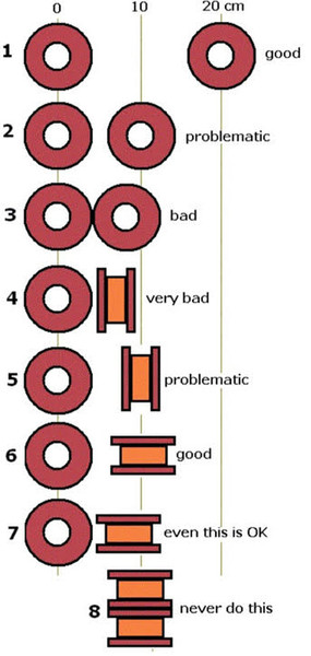
Danny was out of town when I asked but he told me to reach out to Hobbs who got back to me pretty quickly considering it was on the weekend. The best part is they never treated me like the dummy I am rather they are both very helpful in a respectful way. Turns out I had the inductors laid out in a way they would cause them to interfere with each other. He provided a simple to understand chart showing best practices for combining inductors in close proximity. Armed with the new knowledge I went back to MS Paint and rearranged the components and made sure the new arrangement would fit through the hole.
Inductors dos and don’ts
In any case here is the final layout
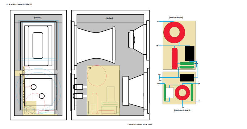
Hobbs confirmed the new layout would work so it was time to build the boards, lay the components out, drill the hole for zip tie, twist things up and solder.
HERE is my RP500M photo album with images that may be helpful to youMS Paint has a unique feature you may not know of where you can view grid lines which basically make it a piece of graph paper where you can scale a project. I used 1 square equaled 1/8th inch. This allowed me to know exactly how large the boards needed to be after I added all the scaled parts. I decided not to just place the boards on top of no rez because there would be no way to secure it to the cabinet, so I ripped a piece of 1x2 down to 1” the thickness of the no rez by the width of the boards. This enabled me to make for a contact point with the speaker cabinet. I used hot glue to attach the support to the boards and the side wall of the cabinets. There was not enough room to add one to the horizontal board as it would bring the upper inductor in contact with the tuned port, so instead of no rez on the floor I used a piece of the factory poly fiber fill removed from the cabinet underneath it. With all parts secured and twisted up I soldered it up. (see album)
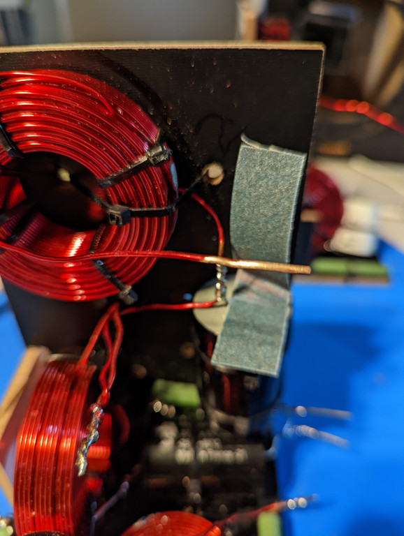
PRO TIP: If you are a noob like me, a noob, it’s important to point out here that the red wire of the inductor coils needs stripped where every solder connection is made before soldering followed up by adding shrink wrap over any exposed copper to prevent oxidation in the future which would degrade the signal. The red is an enamel coating that I’ve heard tell alcohol would strip. I tried isopropyl, and denatured alcohol which didn’t work. Then I tried acetone and lacquer thinner also didn’t work. The best way I have found to strip off the read enamel is Emory cloth which can be found at any hardware store. Basically, it is sand paper which I presume would also work but I had some of the stuff in my plumbing kit in the garage which is commonly used to prep copper pipe before soldiering. If you don’t have some get some.
Based on where the new crossover is being placed in the cabinet, I understood no rez would be placed on the sides and the top of the inside of speaker cabinets only. A word of caution if you are doing it my way. Do not put both sides of the no rez in before putting the crossover in there. I made this mistake on the first one and although I did not have to take out the one side there was a point there where I thought I’d have to. So, consider that a Noob tip as the 2nd one went much easier than the 1st.
Even though these cabinet are quite small you might think the no rez can go in there in one piece and you would be wrong. It’s best the spit the width in half and rip the no rez accordingly. I went with 3.875” wide strips which went front to back. I had the miter out foam where the support brackets were before placing but this assured the entire surface front to back was covered.
With most the no rez in place it was time to measure and cut the copper wire for speakers and tube connectors. For tips on that Dany’s videos are a great resource. (see link above) With this upgrade you will have two leads going directly to the tube connectors and I was concerned that two 12ga wires twisted together would fit in there. I can say they fit easily if twisted tightly. Tin first then crimp and solder to finish the connection. Don’t forget the shrink warp for tube connectors and speakers and always tin the wire first before soldering them together. Other than that you will need a 7/16” drill bit not included in most assorted drill bit set so head to you hardware store. Also you will have to secure the plastic for the binding post in a vice or something while drilling it.
That’s it, screw back in you speakers binding and tuned ports everything back in hook it up and enjoy.
Hope this helps. PM me if any questions.
If you need a full size image just ask. If you need an image with the values of the components illustrated you will have to provide me an image of the schematic you got with your purchase with your forum persona and date handwritten on it, Send it to me via PM before I can do that.