Purpose:* To share my experience repairing the 3Be's power supply and replacing aging tantalum capacitors.
Equipment: * Bryston 3Be stereo amplifier, serial number 330033.
 Figure 1: Bryston 3Be front view after repairs - photo taken January 2023Background:
* This 3Be power-amp I purchased new in 1992 from Loyalty Sound Ltd in Calgary, Canada. Overall, I was very pleased with the performance of this power amplifier throughout 10 years of worldwide assignments. Although it was in full working condition, sadly I had to put my 3Be into storage in 2001 due to shortage of living space.
* Early 2022, brought my 3Be out of storage and powered it up for the first time in 20 years, and immediately shut it down when noticed smoke emission.
* As the quotation to ship by courier one-way from Japan to Canada was JPY 70,000 (approx. USD 600 then) and express service was limited during the pandemic, I decided to investigate and attempt repair if possible.
Symptoms (apart from the smoke emission): * Both channels dead with Red LEDs illuminated.
Diagnosis: * Measured voltage at LM317 Positive Regulator: Vin = +55 VDC, Vout = +17.7 VDC. Good.
* Measured voltage at LM337 Negative Regulator; Vin = -55 VDC, Vout =
-0.7 VDC. Not good.* Observed the 1.5uF tantalum capacitor on negative voltage side was burned (Fig. 2).
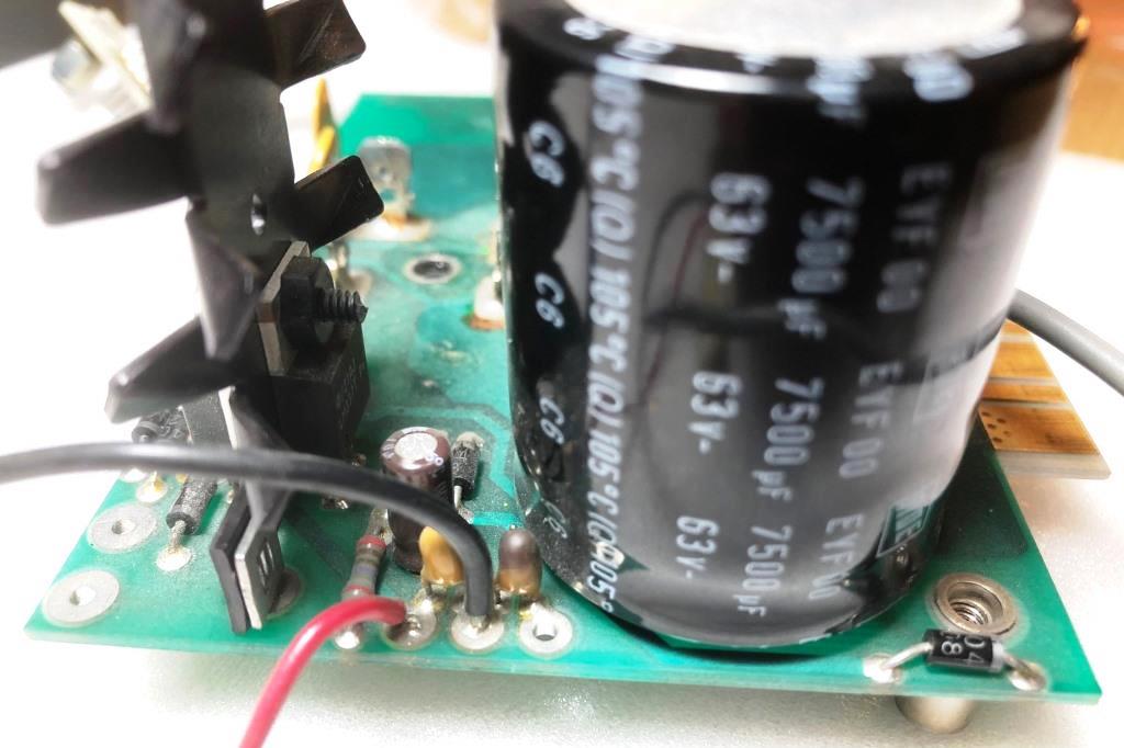 Figure 2: Tantalum capacitors (Left capacitor normal color, Right capacitor discolored/burnt). Repair:
* To be aware at all times of safety to equipment and yourself, when powered up both AC line voltage and +/- 55 VDC is present!
* Desoldered and removed both tantalum capacitors, replaced with new tantalums having same rating as original, 1.5 uF / 35V (Fig. 3).
* Repeated this for the other channel, replacing both tantalum capacitors with new.
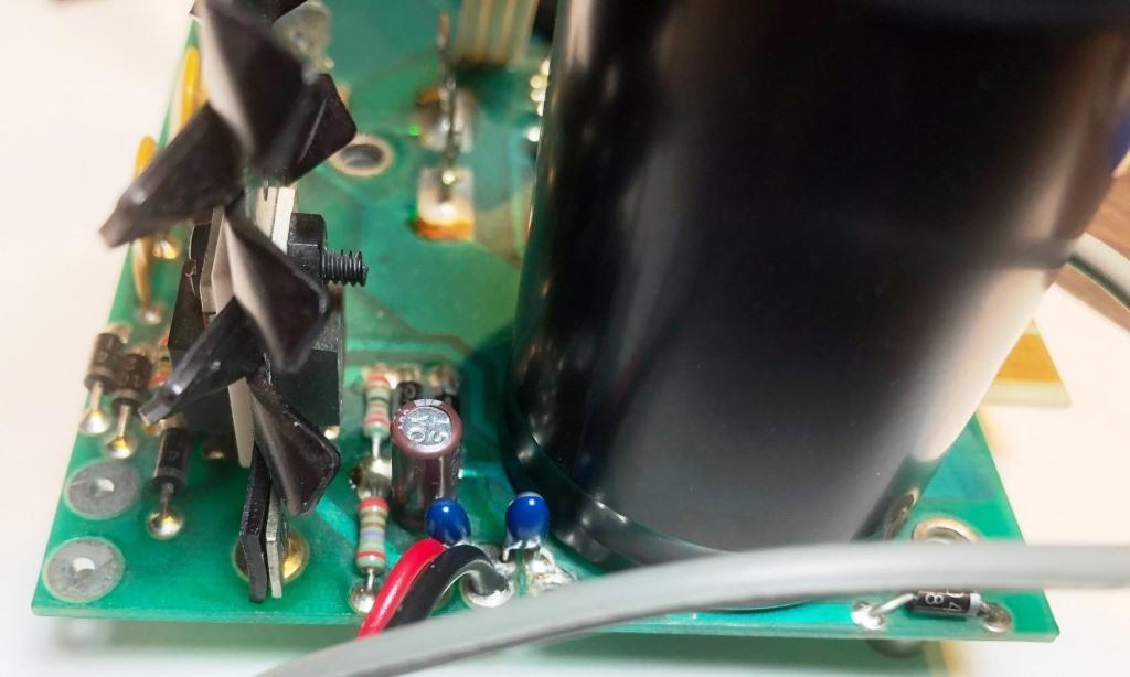 Figure 3: Replaced both tantalum capacitors (Blue color).Other power supply repair:
* To be honest I didn't find anything else wrong in the power supplies, and although it may not have been necessary, decided to changeout the large power-supply capacitors due to equipment age of 30 years, of which 20 years was in storage.
* The original power supply fitted capacitors (qty 4) were made by Roederstien of Germany with rating 7,500 uF, 63 V, 105 Deg C (Fig. 4).
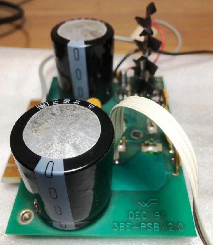 Figure 4. Original dual capacitors fitted to each channel, RDE 7,500 uF, 63 V (note board markings Dec 91, 3BE-PSB/2.0).
* Unable to find Roederstein capacitors of the same electrical rating and mounting type having 3 straight leads, I replaced with new Cornell-Dublier SLP103M063H9P3, having rating 10,000 uF, 63 V, 105 Deg C, knowing that modern electrolytic capacitors typically employ 2 snap-in pins requiring 2 mm dia. PCB holes (Fig 5).
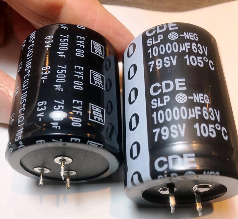 Figure 5. Original RDE with 3 straight leads as fitted (left), replacement CDE having 2 snap-in pins - note larger diameter pins (right).
 * To fit the new capacitors some local modifications were required to the PC board.
* After desoldering and removing the two RDE capacitors, carefully enlarged the positive and negative mounting holes using a fresh 2mm drill bit (Fig 6). The third hole becomes redundant and was left as is.
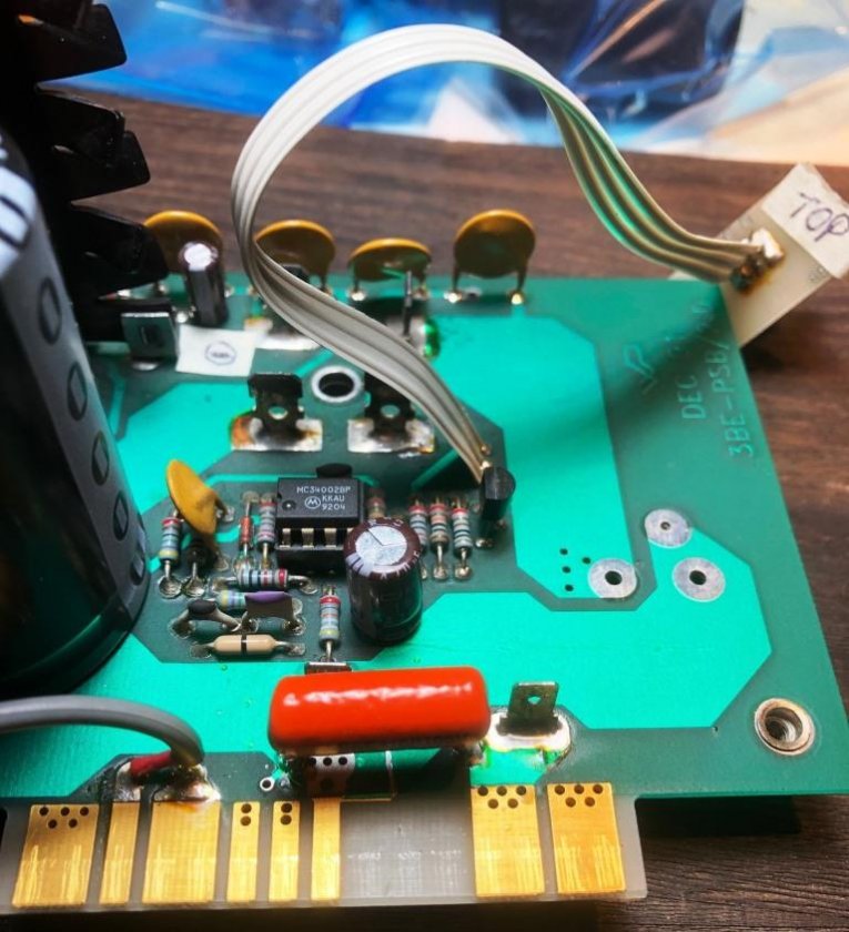 Figure 6. Two PCB holes drilled out to 2mm (the third hole is now redundant and does not need to be enlarged).
* With this modification the new capacitors fit nicely (Fig 7). Ensure to double check all polarities are correct before soldering the snap-in pins in place.
 Figure 7. Replacement capacitor mounted. Caveat:
* While this makes for a neat and tidy mechanical mounting of a modern electrolytic capacitor replacement, a consequence of enlarging the mounting holes to the standard 2mm dia. is the loss of thru-hole conductance, resulting in loss of electrical connection on one side of the capacitor.
* One way to restore this connection is to run a jumper wire connecting the 2 outer pins of each capacitor back to the common ground (Fig 8). This is not to make any changes to the circuit, just to restore the connections originally made by the PCB traces.
* Although this was not my best soldering effort as it was meant to be a trial to confirm the jumper wire installation worked, it did work and has been working well without issue ever since.
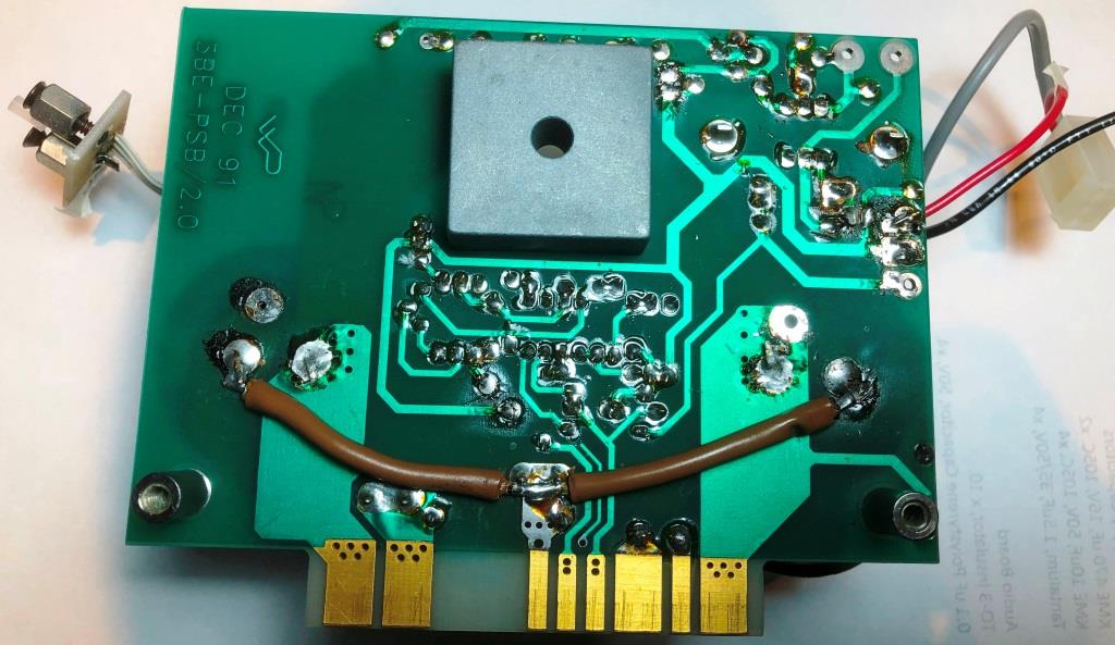 Figure 8. Installation of jumper wire on the underside of the power supply PCB.Audio board repair:
* After repairing the power supply the amplifier worked reliably, then after some 4-months of operation suddenly one audio channel went dead.
* Found the 33V Zener diode voltages supplying the input differential pairs was unstable. Problem traced to the 1.5 uF / 35V tantalum capacitors paralleled across the Zener diodes had become discolored and were leaking (Fig 9).
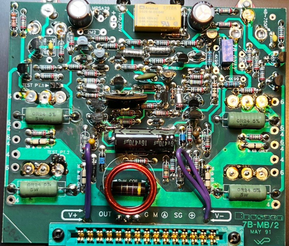
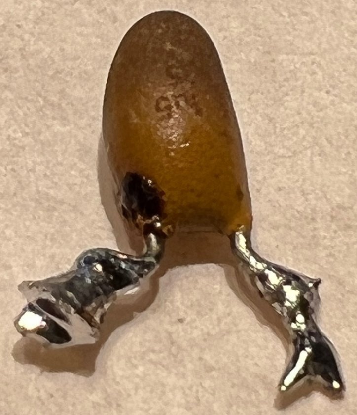 Figure 9. Two tantalum capacitors on either side of the black axial capacitor, closeup of a removed tantalum burnt/leaking.
 * Although my local supplier had 1.5 uF / 35V tantalum capacitors in stock, to install a 35V rated component in a 33V operation I felt was borderline so purchased instead higher rated 2.2 uF / 50V tantalum capacitors (my local supplier had sold out of 1.5 uF / 50V rated tantalums). Although these new capacitors were slightly larger in size it was straightforward to install them on the audio board (Fig 10).
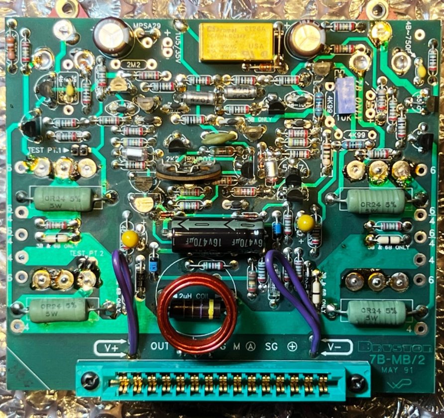 Figure 10. Two new tantalum capacitors installed on audio board (installation repeated for other board).Final notes:
* The reason for this writing is to share my experience repairing the power supply of a Bryston 3Be and replacing the aging tantalum capacitors. It's not an endorsement of any component supplier or to bypass factory repairs, just to share what worked for me.
* Interesting to note, after 30-years all 8 tantalum capacitors (4 in the power supplies, 4 in the audio boards) had to be replaced, whereas all other components remain fully operational. Possibly the original series of tantalum capacitors may have been from a weak batch.
* At time of this writing, the power supply repairs have been operating without issue for 9 months now, the audio board repairs have been operating without issue for 5 months now.
* Apart from the upgrade of power supply capacitors from 7,500 uF to 10,000 uF (Fig 5) and the local modification to the PC board to accommodate these larger capacitors (Figs 6, 8), no tweaks or enhancements were made.
* And yes, my repaired 3Be power amplifier is fully operational and sounds great just like it used to!


