History* In October 1983 I purchased the following hi-end audio equipment from Straight Gain Electronics, Toronto, ON.
1) Oracle Premiere turntable, serial number 0114.
2) Kiseki Blue MC cartridge (fitted to Oracle Finale tonearm).
3) Spectral DMC-10 preamplifier, serial number 10491.
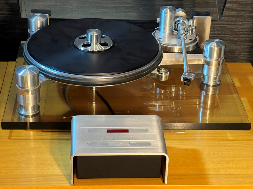 Figure 1. Oracle Premiere turntable, Finale tonearm and control unit, serial number 0114 - photo taken August 2023.
* Overall, I was very pleased with the performance of this equipment throughout 18 years of worldwide assignments throughout Canada, Japan, UAE and UK. Although it was in full working condition, sadly I had to put all my stereo equipment into storage in 2001 due to shortage of living space.
* In 2021 I brought my equipment out of storage and powered it up for the first time in 20 years but found the turntable inoperative.
Control Unit Restoration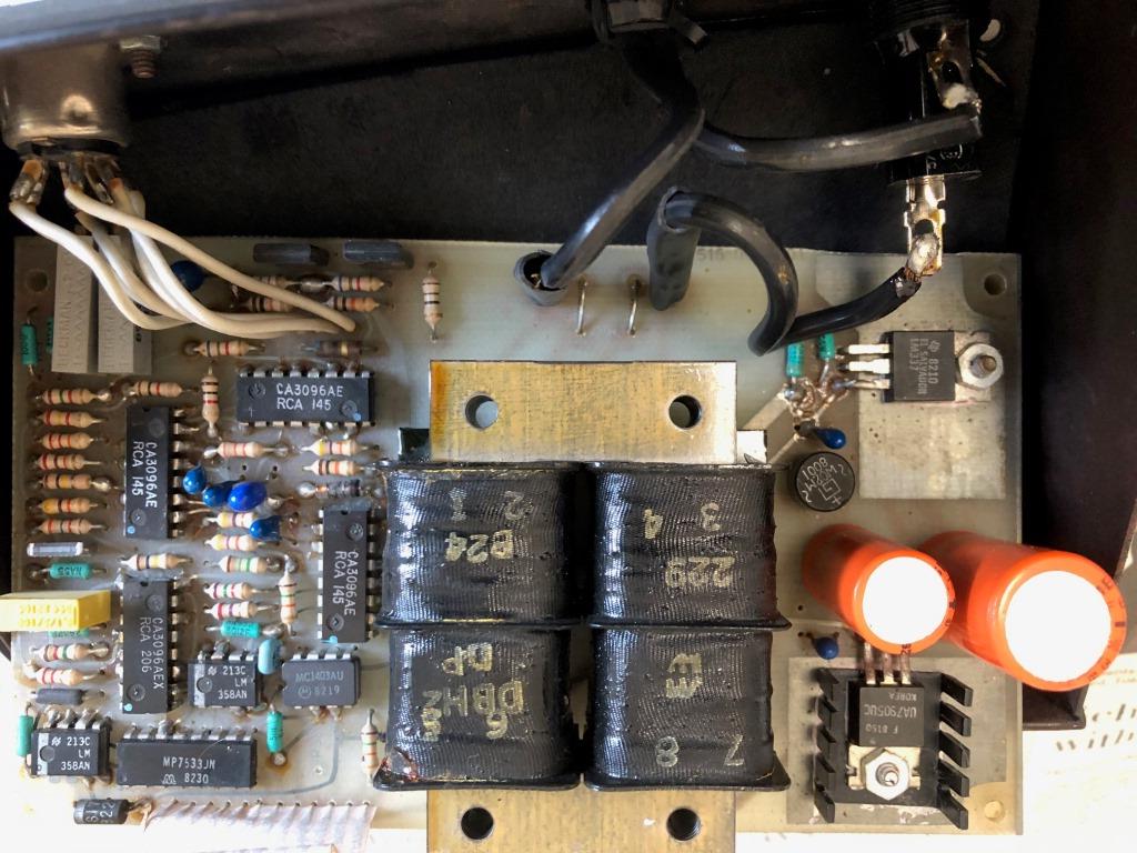 Figure 2. Internal view of Control Unit's circuit board showing original components.
* With the kind assistance from Oracle Audio (Jacques Riendeau) who supplied a full set of circuit diagrams for the Oracle Premiere's control unit, I could repair the control unit by replacing most of the electrolytic capacitors with voltage ratings equal or higher than original, also the broken fuse holder and the -5V regulator IC10.
* Three capacitors were replaced in the control circuit:
- C3, 22 mfd tantalum
- C4, 22 mfd tantalum
- C5, 1.5 mfd tantalum
* Four capacitors were replaced in the power supply:
- C10, 1 mfd tantalum*
- C11, 470 mfd radial electrolytic
- C12, 1 mfd tantalum*
- C13, 470 mfd radial electrolytic
* Of the two tantalum capacitors C10 and C12 in the power supply, one of these measured short-circuit and was probably the cause of the control unit failure.
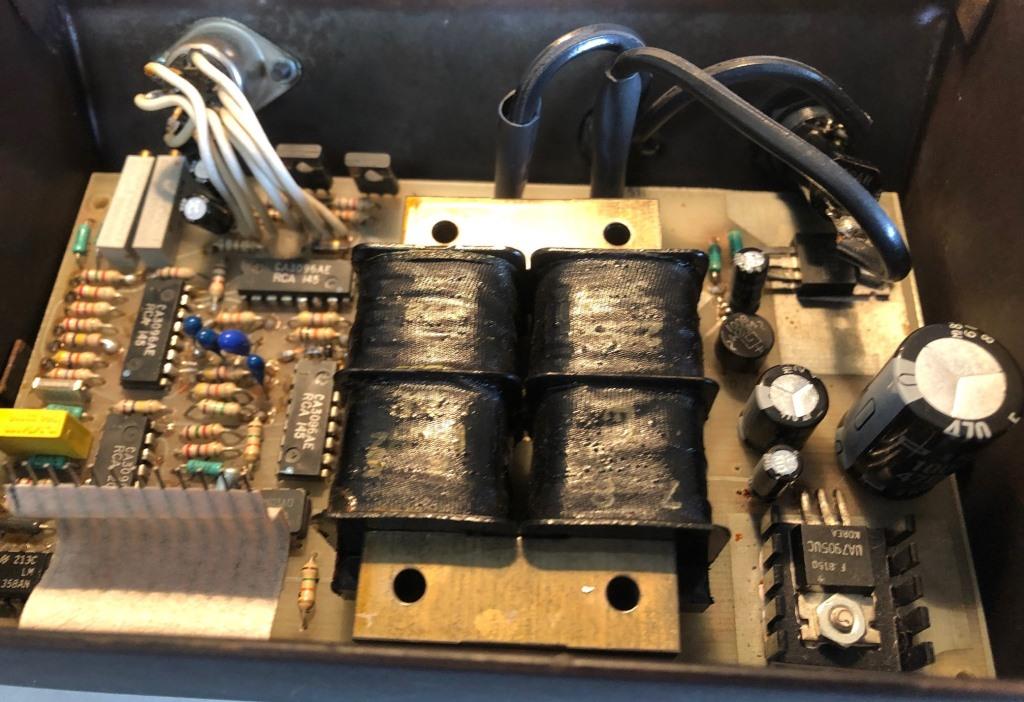 Figure 3. Internal view of Control Unit after replacing the fuse holder and several of the capacitors.
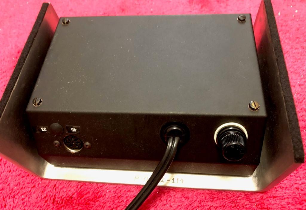 Figure 4. Underside of Control Unit after replacing the fuse holder.Turntable Restoration
* With the Control Unit repaired I could now play vinyl records again!
* However, during listening I could detect excessive wow & flutter, furthermore a test with the drive belt removed and spinning the platter by hand observed the platter would come to rest after only a single revolution, an indication of friction in the main bearing.
* Removing the main bearing (requires a 9/64-inch hex-wrench) for inspection (Fig. 5), found the spindle was quite difficult to rotate by hand.
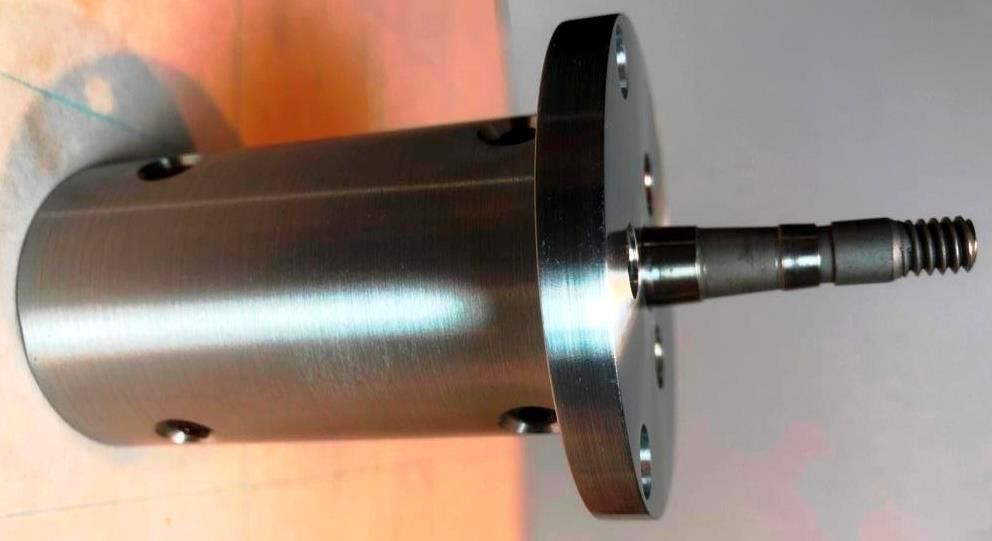 Figure 5. Side view of main bearing assembly.
* Removing the spindle from the bearing housing and carefully cleaning several times inside of the bearing's bushings and the tungsten carbide tip of the spindle with isopropyl alcohol and Q-tips, then drying and lightly lubricating with sewing machine oil the rotation of the spindle improved substantially.
* Unfortunately, there was some remaining stiction that prevented the spindle from spinning freely. Upon inspecting the spindle's shaft, it showed a small circular wear mark at the lower end of the spindle where it makes contact at the top of the bearing's lower bushing (Fig. 6).
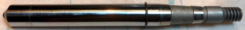 Figure 6. Spindle shaft showing a circular wear mark at the lower end - far left side of photo.
* Upon consulting my findings with Jacques Riendeau, he explained due to the tight manufacturing tolerances of the bearing assembly it would be best to have it re-dressed back at Oracle Audio's factory in Sherbrooke, PC. This I did, shipping just the main bearing assembly back to Oracle Audio.
* As the service work to re-dress and recalibrate the main bearing was not expensive, I took this opportunity to order other maintenance and upgrade items with the return shipment. Facture/Invoice: 216463 of May, 2022 included:
a) Record main bearing calibrated (as discussed)
b) Maintenance Kit with Springs
c) MK VI Record Clamp (upgrade item)
d) Hard Acrylic Mat (upgrade item)
* Reassembling the repaired main bearing and installing the new parts was straightforward, pleased to report the platter now spins smoothly. Using the AnalogMagik test program LP confirmed both the speed and wow & flutter to be well within manufacturer fs specifications (Fig. 7) - even more satisfying considering this turntable is 40 years old.
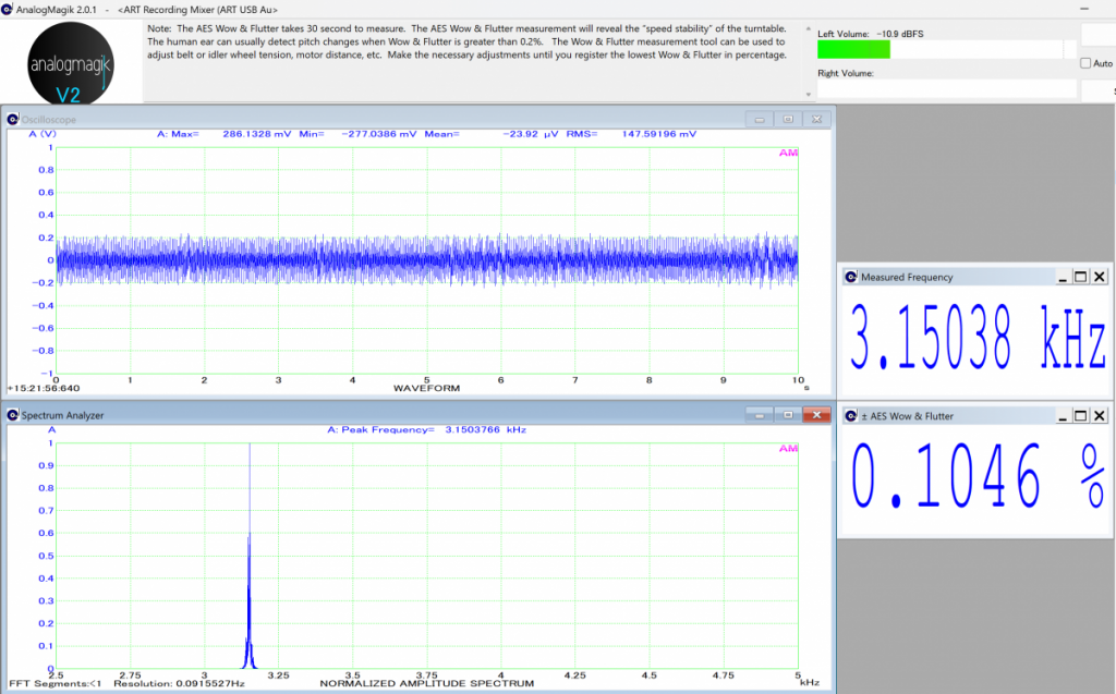 Figure 7. Measured Frequency (3150 Hz conforms to 33 1/3 rpm)
,
Wow & Flutter.* Four springs were included in the maintenance kit, coloured from stiffest to softest: Green, Red, Yellow, and White. There is an option to order an even stiffer Blue spring, but this was not needed.
* Following Oracle's instruction video for assembling and adjusting the spring suspension system, I installed the Green stiffest spring on the Right side by the tonearm, Yellow spring at Left front, and Red spring at Left rear (the White coloured softest spring was not used). After adjusting the spring's stiffness, the distance between the top face of the acrylic base and the bottom of the suspension housing was set to 20.7mm (0.815 in.) for all three towers (Fig. 8).
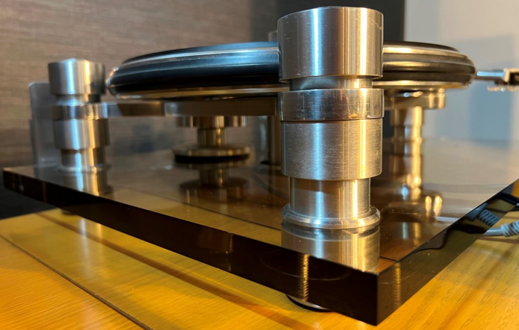 Figure 8. After optimizing spring stiffness, distance to suspension housings set to 20.7mm - photo taken August 2023.
 * I used the AnalogMagik Vibration test track to evaluate the effectiveness of these new springs and drive belt that came with the maintenance kit (Fig. 9).
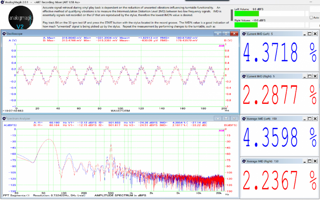 Figure 9. Measured Vibration levels.
* As the original fitted Kiseki Blue cartridge was 40 years old, I replaced it with a new Phasemation PP-2000 cartridge (Fig. 10).
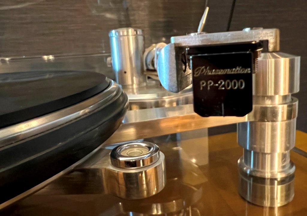 Figure 10. Phasemation PP-2000 Cartridge fitted to Oracle Finale Tonearm - photo taken August 2023.
* With the new Phasemation cartridge fitted to the original Oracle Finale tonearm, overall resonance (cartridge plus tonearm) measured between 9 and 10 Hz (Fig. 11). Commercial literature gives guidelines for system resonance to ideally fall between 8 Hz and 12 Hz. Their explanation is that resonances lower than say 6~7 Hz may be amplified by record warps, while resonances higher than say 14 Hz may interact with low frequency music such as organ notes.
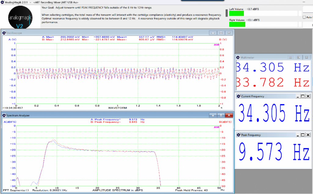 Figure 11. Measured Resonance of Cartridge with Tonearm.Tonearm wiring
* During the installation of the new cartridge, out of curiosity I performed a continuity check of the tonearm's internal wiring.
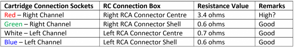 Table 1. Tonearm wiring resistance measurements.
* To determine the internal resistance of the Right channel's red lead, I subtracted the test lead's resistance of 0.23 ohms from 3.63 ohms resistance measured from the red lead cartridge socket to RC connector box Right channel, i.e., 3.63 - 0.23 = 3.4 ohms internal resistance (Fig. 12).
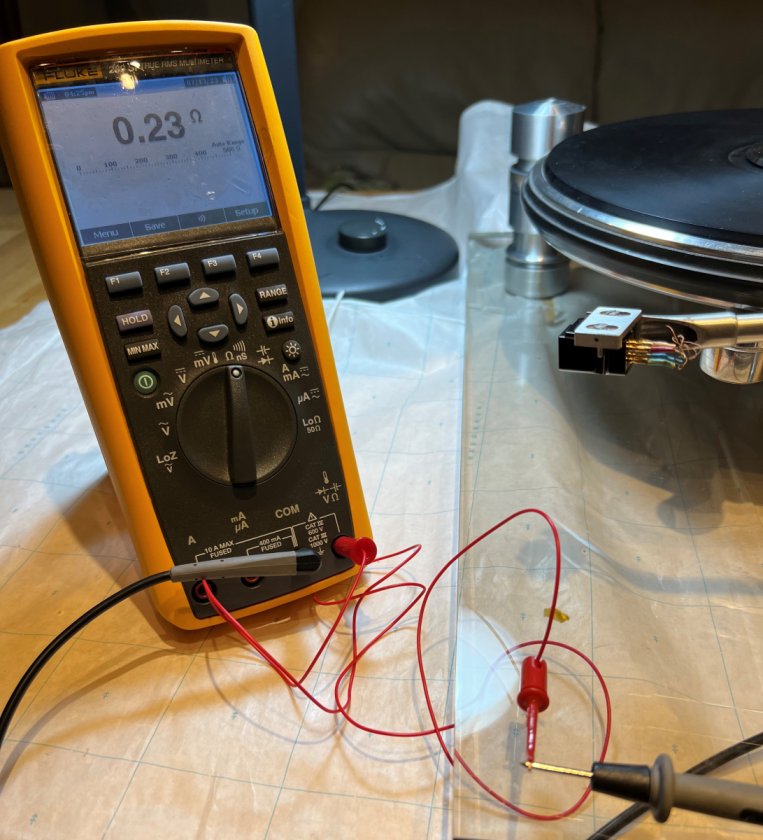
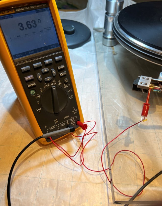 Figure 12. Resistance check of shorted test leads, overall resistance measurement of Right channel red lead.
* Close inspection of the solder connections at both the cartridge connector sockets and inside the RC compensation box revealed nothing untoward with the solder joints. Gently flexing the Right channel connections and wiring, moving the tonearm back and forth etc. showed resistance unchanged at 3.4 ohms.
* As a check on the integrity of the red wire's solder joints, I carefully scrapped off a tiny portion of the red Litz wire's insulation to expose the bare Litz wire (Fig. 13). The resistance measured directly from the exposed wiring (away from the solder joint) showed the same 3.4 ohms, indicating the solder joint's continuity intact.
* Nevertheless, for the Right channel red wire I re-soldered all joints, inside the RC compensation box, at the RCA connector output, and at the cartridge connector socket. However, the measured resistance was unchanged at 3.4 ohms indicating it could be internal to the tonearm's tube.
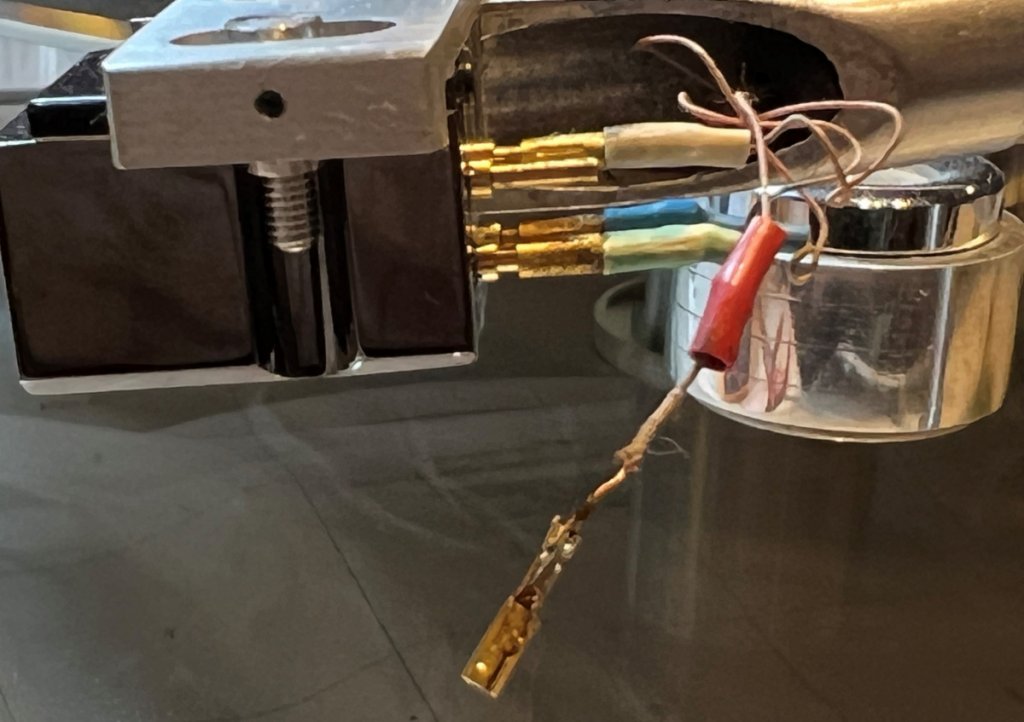
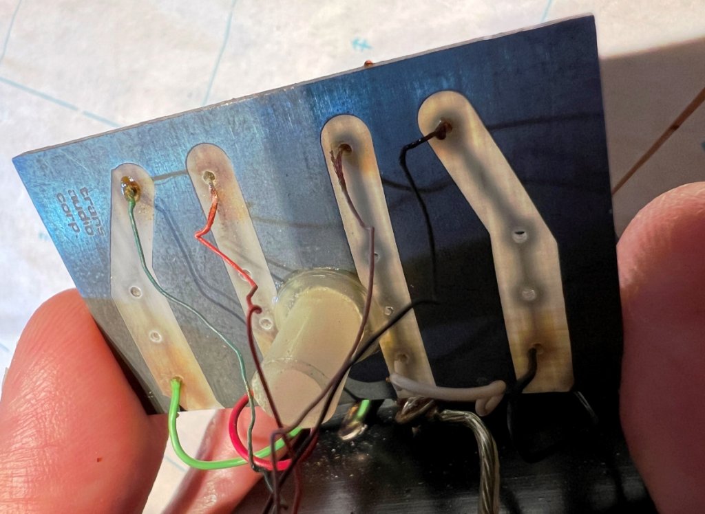 Figure 13. Small portion of insulation removed to measure red wire's resistance between cartridge socket and RC box.
* Periodic checking of the Right channel wiring resistance showed a consistent 3.4 ohms, indicating whatever the cause is, it is stable and not deteriorating.
* To compensate for this, I did some experimenting with the phono loading in my Spectral DMC-10 preamp (Fig. 14), it has internal rocker switch positions which can be set to 10, 30, 100 or 800 ohms loading for MC cartridges, or 47K ohms fixed loading for MM cartridges.
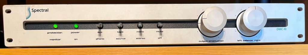 Figure 14. Spectral DMC-10 preamplifier - photo taken July 2023.
* Initially I set the preamp's internal phono loading at 800 ohms (Fig. 15), with the understanding that 3.4 ohms resistance of the Right channel lead would be minor compared to an 800-ohm load.
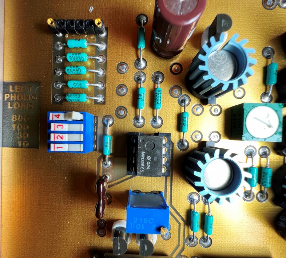 Figure 15. DMC-10 phono loading rocker switches, closeup of rocker switch "4" set to 800-ohm.
* Using the AnalogMagik "Loading" Test track shows the Frequency Response flatness obtained using the different 800-ohm, 100-ohm, 30-ohm and 10-ohm load settings (Figs. 16, 17, 18 and 19 respectively).
 Figure 16. Frequency Response test using 800-ohm loading.
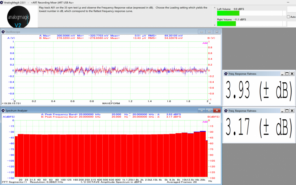 Figure 17. Frequency Response test using 100-ohm loading.
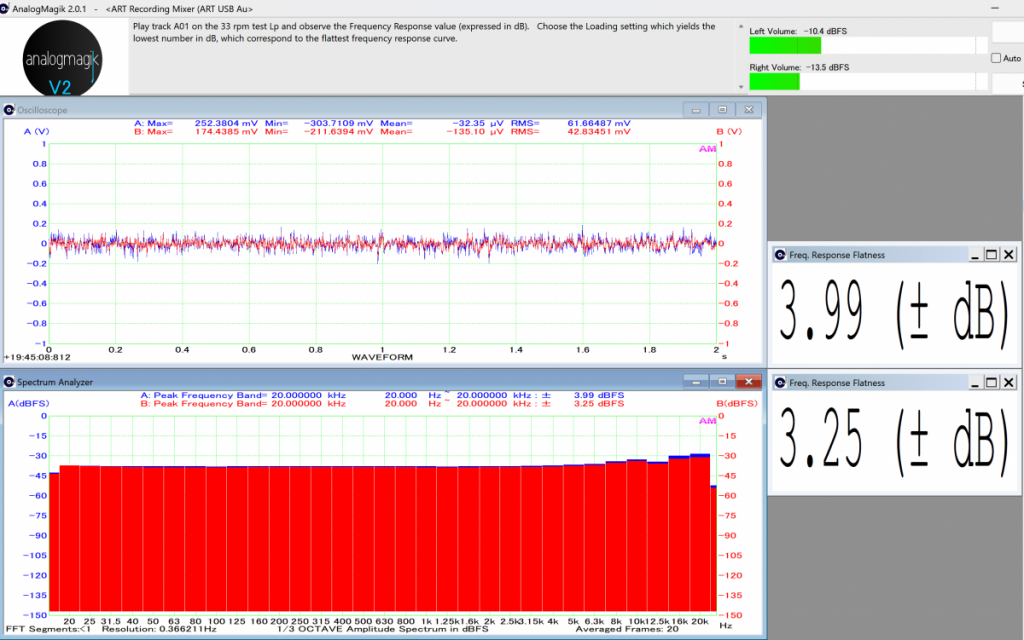 Figure 18. Frequency Response test using 30-ohm loading.
 Figure 19. Frequency Response test using 10-ohm loading.Observations from Loading Test
* Looking at the separation displayed between channels A (Blue) and B (Red), the general trend shows an increasing separation between the Blue and Red colours as the load resistance value is changed, with 800-ohm loading displaying the smallest separation vs. 10-ohm loading displaying the largest separation.
* From this test, best results were obtained with an internal phono loading of 800-ohm (Fig. 16), with this setting retained for all following tests. This finding supports the assumption that 3.4 ohms resistance of the Right channel lead may be relatively minor compared to an 800-ohm load.
Cartridge Alignment Optimization* All the following tests were conducted with an 800-ohm loading in the preamplifier.
* Intermodulation Distortion (IMD) initial results after adjusting the Finale tonearm for Azimuth and Vertical Tracking Angle (VTA), but before adjusting for Zenith Angle are shown in Figure 20.
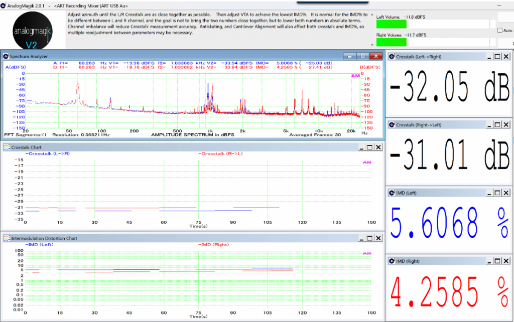 Figure 20. Initial IMD measurements after adjusting for Azimuth and VTA, before adjusting for Zenith Angle.
* The next adjustment was for Zenith Angle, by rotating the cartridge slightly counterclockwise (when viewed from top) produced a positive improvement from start point to final setting (Figs. 21, 22).
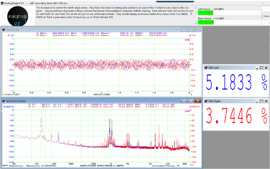 Figure 21. Initial IMD measurements before adjusting for Zenith Angle.
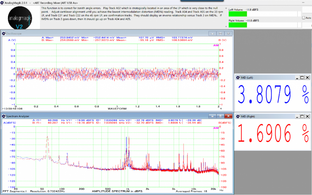 Figure 22. Improved IMD measurements after adjusting for Zenith Angle.
* With the Zenith Angle optimized I then repeated the IMD test for Azimuth and VTA (Fig. 23). This final test compares very favorably against the initial optimization of Azimuth and VTA (Fig. 20). As documented in the AnalogMagik literature, all these settings interact with one another, indeed considerable time and patience is needed to go back and forth between different measurements to achieve the optimum setting.
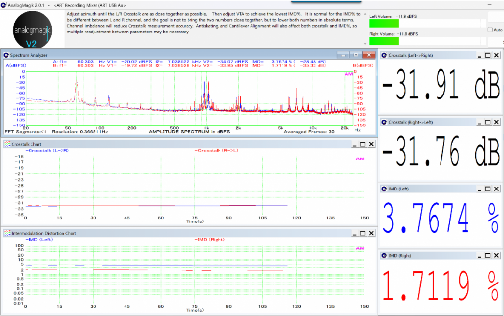 Figure 23. Final IMD measurements for Azimuth and VTA after adjusting for Zenith Angle.
* For reference, the Phasemation PP-2000 brochure specifies its channel separation > 30dB @ 1kHz.
* Comment, in terms of reducing the IMD values, the adjustments I found having the most impact (ranked from lowest to highest impact) were VTA, Azimuth and Zenith Angle. Of course, this was just my finding, depending on the tonearm and cartridge used, the order the tests were performed, and how the adjustments interact with one another the outcome could have been different.
Channel Balance* Based on the final Crosstalk results showing < 0.25 dB difference between L->R and R->L (Fig. 23), I performed the channel balance test which displayed a channel difference approx. 0.5 dB (Fig. 24).
* For reference, the Phasemation PP-2000 brochure specifies its channel balance < 1dB @ 1kHz.
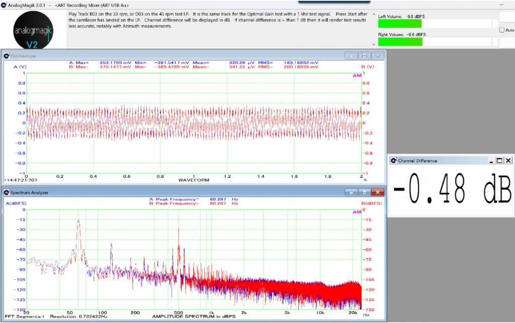 Figure 24. Channel Balance measurements.Final Comments
* With the excellent technical advice provided by Jacques Riendeau at Oracle Audio this has helped me to achieve a successful restoration.
* About the remaining 3.4 ohms resistance observed in the Right channel lead. Discussing again with Jacques Riendeau, while he agreed it shouldn't be like this, we both felt it best to leave alone as I have not been able to detect any impact on sound quality, and from the extremely low crosstalk and channel balance measurements (Figures 23 and 24 respectively) it appears to be of negligible consequence.
* Finally, I am very pleased with the sound quality of my repaired Oracle Premiere turntable fitted with the new PP-2000 cartridge, it's better than I can ever remember, and it performs extremely well with the rest of my audio equipment setup (Spectral DMC-10 pre-amplifier, Threshold PCX crossover feeding a pair of Bryston power amps into Acoustat electrostatic speakers and Acoustat woofer).
Appendix* Restoration of my preamplifier used for these tests is documented in the Audio Circle's Vintage Equipment forum,
"Spectral Model DMC-10 Preamplifier - A Successful Repair".
https://www.audiocircle.com/index.php?topic=186474.0References* Oracle's instruction videos for assembling and adjusting the spring suspension system.
https://www.oracle-audio.com/setup-videos


