Completed Cornet 2 photos

0 Members and 1 Guest are viewing this topic. Read 3102 times.

acceler8

Completed Cornet 2 photos
« on: 26 May 2011, 04:25 pm »
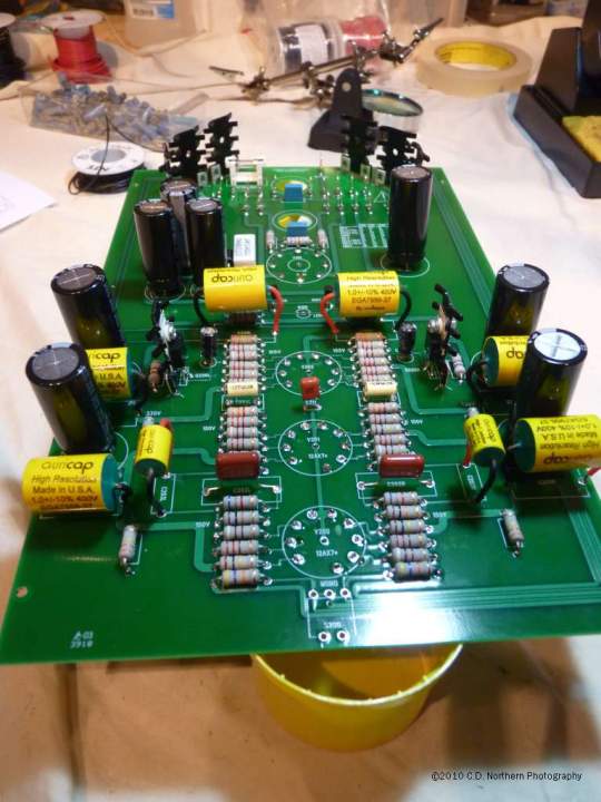
Here are some pictures of my completed Cornet2.

The board (just about complete). I used the recomended AuriCap upgrades


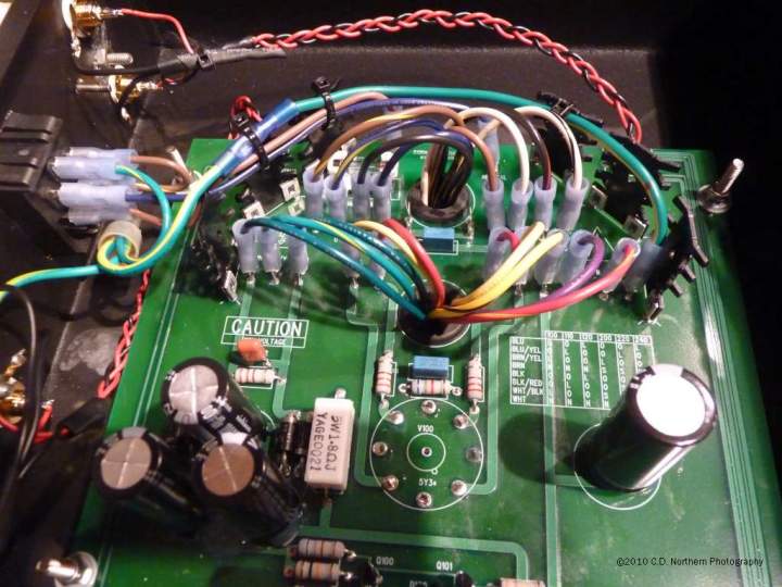
In the chassis.  I'm so glad I went with a larger footprint.


Transformer wiring (medium neat)  8)
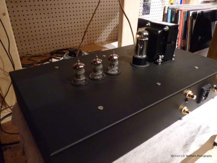

Finished case


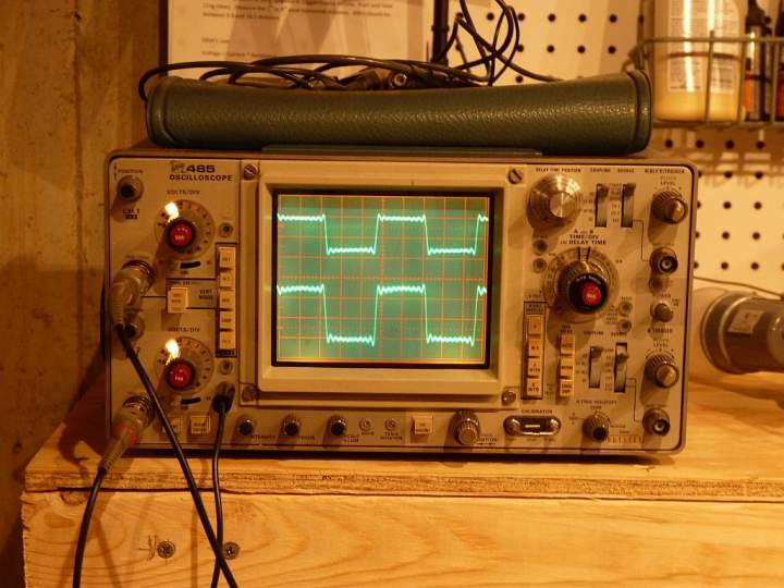
Test signal from cheap laptop sound card.


The square wave is noisy, but the Cornet is very accurate!  Signal Input is on top trace, and output (through a home grown reverse RIAA network) is on bottom.
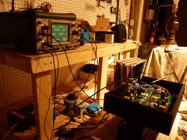

My messy bench.


I've been listening to this beauty for about a month.  I just recently built a reverse RIAA magic box to allow me to test it.

I do have one question.  In the manual, the section on testing shows the 'Residual Distortion' on an oscilloscope.  Does anyone know how to measure that?

Thanks!


rif

  • Full Member
  • Posts: 794
  • Not a cowboy
Re: Completed Cornet 2 photos
« Reply #1 on: 26 May 2011, 08:30 pm »
First off: very cool. It's always good to see traces on a 'scope.

I've always wanted to ask this question, but never have for some reason:

Since you're using a computer to generate the inputs, couldn't you have it do the RIAA and/or inverse function?

acceler8

Re: Completed Cornet 2 photos
« Reply #2 on: 1 Jun 2011, 04:11 pm »
Hmm, that is a good question.  I'm not sure if the results would be the same if the EQ curve were feed in as already reversed.  To get a flat output the input might require more 'offset' than applying the curve after the fact.  Next time I hook up the 'scope I'll see what I can find.

Thanks!

poty

  • Full Member
  • Posts: 616
Re: Completed Cornet 2 photos
« Reply #3 on: 1 Jun 2011, 08:34 pm »
I do have one question.  In the manual, the section on testing shows the 'Residual Distortion' on an oscilloscope.  Does anyone know how to measure that?
You can measure the distortion like any signal on the o'scope. :) I think your question was about how to obtain the residual distortion signal (RDS)? Right? :)
The RDS can be obtained by subtracting clear input signal with appropriate amplitude from the resulting amplified signal, which has noise and distortion in it. I don't know exactly how JH had obtained his picture, but in modern digital world it can be achieved by recording a short interval of clear tone from the output of an amplifier in digital and then in an audio editor subtract the clear tone with the same frequency, phase and amplitude from the recorded signal. The remainings would be the residual distortion.

hagtech

Re: Completed Cornet 2 photos
« Reply #4 on: 8 Jun 2011, 10:18 pm »
You may need to add some electric field shielding between the input leads / connectors and the AC wires.

jh

acceler8

Re: Completed Cornet 2 photos
« Reply #5 on: 9 Aug 2011, 04:16 pm »
You may need to add some electric field shielding between the input leads / connectors and the AC wires.

Great words of advise!  I whittled an aluminum bracket into a funny shape and bolted it to my threaded stand-offs.  Then I cut some copper sheeting to put on the front and back (held on with aluminum duct tape).  My system was quiet before, but after this mod I was amazed!  At first I thought something was wrong with my amp because even with my ear right next to the tweeter there was no noise/hiss what so ever!

Thanks!