Bryston 2B Power Amplifier repair - Hints and Lessons Learned

0 Members and 2 Guests are viewing this topic. Read 2087 times.

John Tulett

  • Jr. Member
  • Posts: 19
  • Fascinated by vintage audio equipment
Bryston 2B Power Amplifier repair - Hints and Lessons Learned

Purpose:
* To share my experience repairing an early series of the Bryston 2B power amplifier.

Equipment:
* Bryston 2B stereo amplifier, serial number 2930.


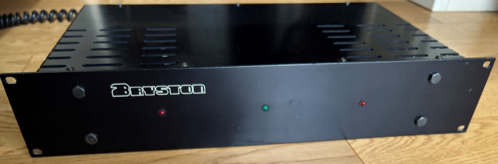
Figure 1: Bryston 2B front view after repairs - photo taken February 2023.

Background:
* This 2B power-amp was manufactured 1978 which I purchased new in February 1979 from Dave Ross Stereo in Kingston, Canada.  Overall, I was very pleased with the performance of this power amplifier throughout several years of worldwide assignments, faultless operation even in harsh climates.
* Although it was in full working condition, sadly I had to put my 2B into storage in 2001 due to a shortage of living space.
* Early 2022 brought my 2B out of storage and powered it up for the first time in 20 years, however the left channel was completely dead.  As the 2B's components are easy to access decided to attempt repairing it. 

Diagnosis of Left Channel:
* Glass cartridge fuse 3.15A / 30 mm blown.
* Twin electrolytic capacitors Mallory 6,000 uF / 40 VDC (Fig. 2) measured 3,200 uF and 5,000 uF.
* Power transistor Motorola NPN 2N3773 Emitter-Collector measured short-circuit.
* Power transistor Motorola PNP 2N6609 Base-Emitter measured open-circuit.


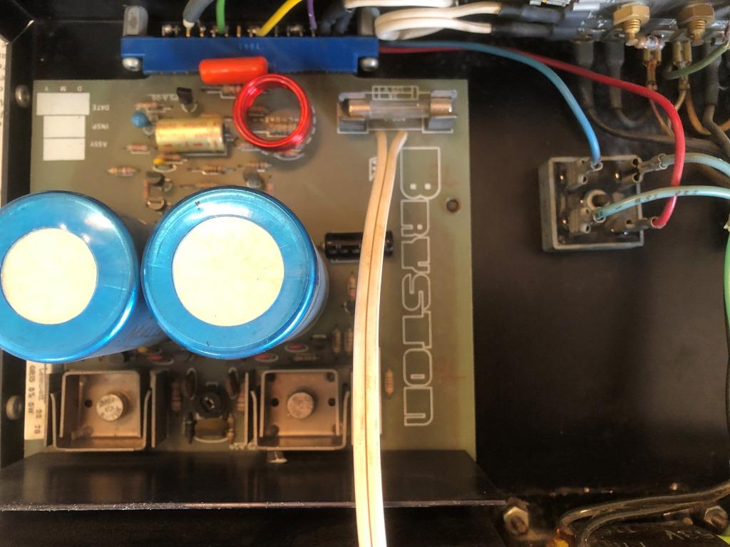
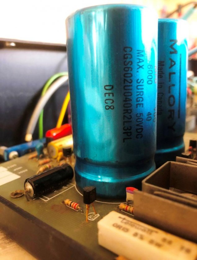
Figure 2: Original power supply capacitors, 6000 uF / 40 VDC - cartridge fuse is on circuit board's right-hand side.

Repair:
* To be aware at all times of safety to equipment and yourself, when powered up both AC line voltage and +/- 37.5 VDC is present.
* The power supply capacitors I replaced with new Kemet ALS80A 103 DB 063, a plain can type that readily installs on the 2B circuit board, with added benefit of higher rating 10,000 uF / 63V, 105 Deg C. 
* Please take care when ordering capacitor replacements.  The Kemet ALS81A series have a threaded mounting stud (which is not needed), that makes for a longer overall length and may not fit within the 2B chassis - which I found out the hard way.  Whereas the Kemet ALS80A series being a shorter length plain can type, even with a higher capacitance rating fits nicely within the dimensions of the 2B chassis (Fig. 3).
 

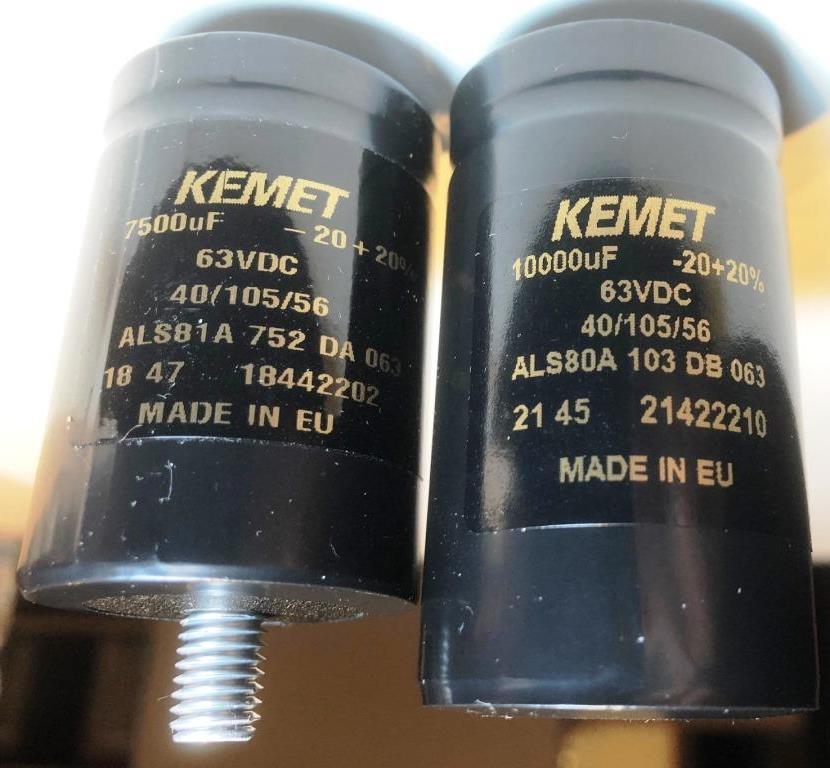
Figure 3: ALS81A 7500uF with threaded mounting stud (left), ALS80A 10000uF plain can type (right).

* The three smaller electrolytic and two tantalum capacitors on each circuit board were tested and all within specification and functional, but as a precaution replaced them with higher grade new. 
* Left channel power transistor 2N3773 replaced with higher rated MJ15024.  Power transistor 2N6609 replaced with higher rated MJ15025.  Renewed the TO-3 size mica insulators and silicon insulating grease. 
* Replaced glass cartridge fuse with a standard 3A / 30 mm type.
* The original 10K bias potentiometer was an open-face type (Fig. 2) and although still working had captured some dust over the years, as precaution replaced with closed type potentiometer of same rating 10K (Fig 4).


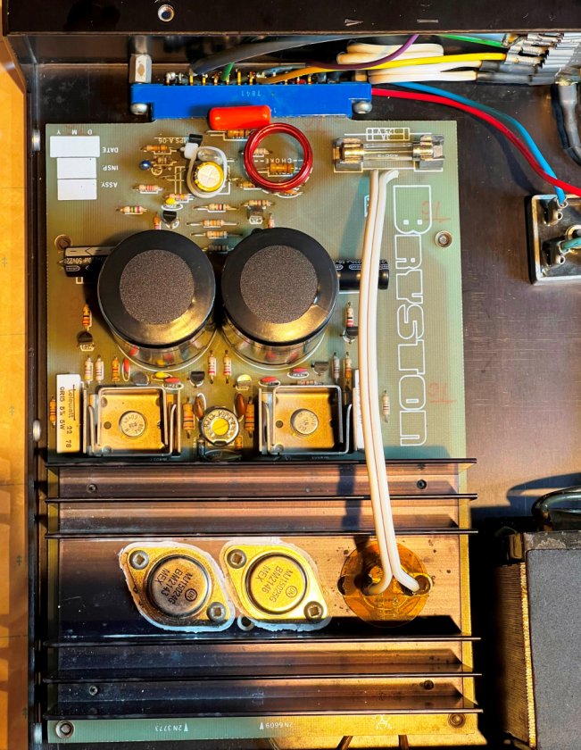
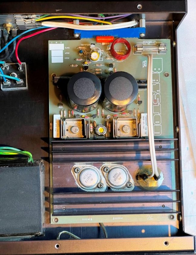
Figure 4: Left and right channel boards with closed type bias potentiometers installed.

* Except for the power transistors, all component replacements were repeated for the right channel.


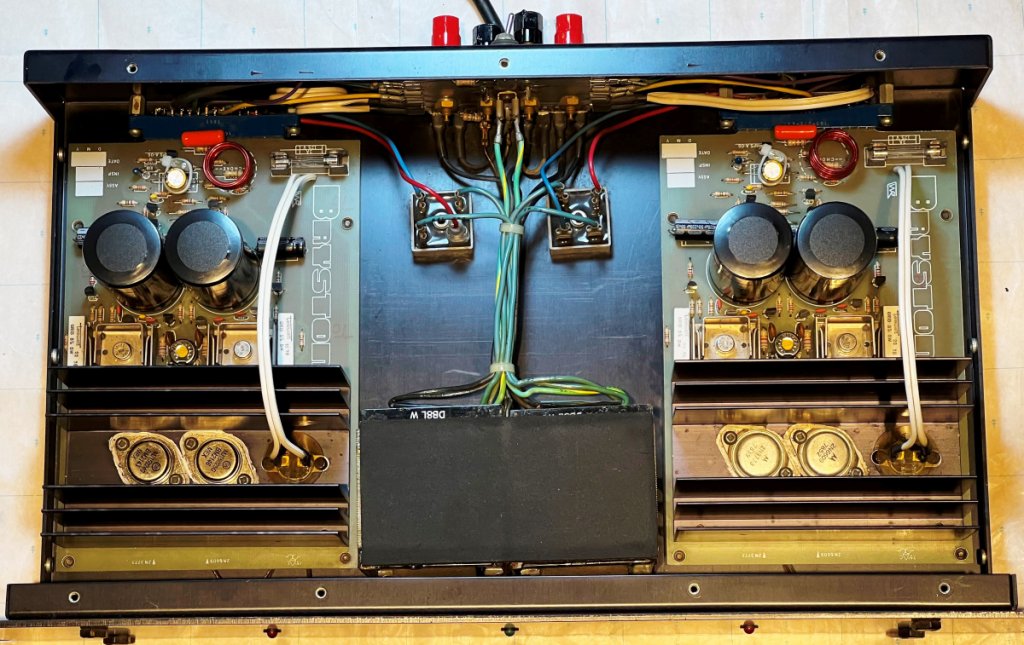
Figure 5: Internal view after repairs completed - new MJ15024/MJ15025 power transistors on left channel heatsink.

Measurements after repairs:
* Whenever replacing the bias potentiometer and/or the power transistors it requires a resetting of the bias current.  The instructions for setting the bias level are well documented in Bryston's 2B Technical Data sheet "Burn-in Procedure".
* Ensure the AC supply voltage is stable before performing this measurement.
* With the amplifier fully warmed up after a few hours operating, I set both channel's bias values to between 9 ~ 10 mV, measured between the V+ red terminal of the bridge rectifier and the 100-ohm resistor.  This setting proved to be the most stable, even when driven at the highest output power level. 
* Hint, patience is required for the bias adjustment. While changing the bias potentiometer setting induces an immediate electrical change, with thermal lag it may take a few minutes for the temperature feedback sensing to fully respond.  Suggest when changing the bias current setting, to do it a small step at a time, then wait for the system to stabilize and re-check the measurement.  When I first set the bias, I didn't pay attention to this and as a result the amplifier became very hot after a few hours of playing music.
* As a general guideline, if you place your hand on the 2B's top panel after a few hours of playing music and it's warm to the touch, the bias current is likely okay.   But if the surface is hot to the touch and/or the power supply is overloaded causing the chassis to hum then the bias current is likely running too high.   
* Last check, with the analog inputs shorted to ground, the DC offset measured across the output terminals was 4mV left channel and 6 mV right channel (should be less than 50mV). 

Final notes:
* The reason for this writing is to share my experience repairing a Bryston 2B power amplifier.  It's not an endorsement of any component supplier or to bypass factory repairs, just to share what worked for me.  At time of this writing the repairs have been operating without issue for 9 months now.
* And finally, pleased to report my repaired 2B is fully operational and sounds great just like it used to!

Rocket

Hi,

Thank you for posting your repair to your Bryston Amplifier. I found it an interesting read and I'm so jealous of your electronic repair skills :).

Cheers Rod

John Tulett

  • Jr. Member
  • Posts: 19
  • Fascinated by vintage audio equipment
Hi,

Thank you for posting your repair to your Bryston Amplifier. I found it an interesting read and I'm so jealous of your electronic repair skills :).

Cheers Rod
Dear Rod,

Thank you for your kind remarks, you might have seen I posted a related document “Bryston 3Be Power Amplifier repair - Hints and Lessons Learned”.
This is the first time I have done a restoration of the Bryston power amplifiers and each one took me several months to complete so I’m still learning, but I have found their amplifiers to be well built pieces of equipment and not so difficult to work on.  Good news though if you’re stuck they have a well-respected after sales service.

Thank you,
John

REDGUUZ

  • Jr. Member
  • Posts: 9
Dear John,

Thank you for  your very  informative "Lessons Learned" on the overhaul of your Bryston 2B  and also your similar  contribution on a Bryston  3Be.   Both write ups were very useful for me (also the accompanying photo's).!

Question for you:

I have a question on preventive capacitor replacement in a Bryston 4B ST Amp i.e.
Could you please comment on my selected tentative replacement types for the axial, radial electrolytic capacitors on the "Amp PCB" and the "extension PCB" boards??

(NB the main Power Supply  buffer capacitors (8 X Nichicon 5600 uF,  100V,  105 deg. C) still measure fine (capacitance and ESR) , and I do not intend to replace those, for the time being.

The small Elco's ones on the boards are probably OK as well, but I would like to replace them preemptively, just to be sure!
This  especially applies for the tantalum caps, since I have bad experiences with those in Tektronix and STUDER equipment;  The voltage de-rating (now after 40-45 years) seem to have been too low, and they might/do fail with massive short-circuits), as you have experienced, yourselves.

Background

I recently purchased from a Medical Doctor, a Bryston 4B (originally an NBR)  vintage: Mid 1990's, but upgraded by BRYSTON Canada in late 2004 to ST specs.
(the special Bryston box used for sending the Amp to and fro Canada is still there, inclusive of the Rep details who handled the order in Canada!).

Talking about an excellent service: The importer in the Netherlands (MaFiCo)  sent me, a few weeks ago, free of charge, 14 screws for the top plate, because somebody had damaged them, by not using a proper Robbertson socket.

Anyhow, my Bryston 4B - ST "Metisse " is playing fine with my transmission line speakers (IMF Studio Monitor, later TDL).
I'm happy with the Amp!

Back to the electrolytic capacitors:

There are (see schematic):
8 X Axial 470uF 16V 
4 X radial 470 uF  16V
2 X axial 2200 uF  16V
4 Tantalums  1.5 uF 35V

There are nowadays preciously  few suppliers for axial capacitors.

I selected Vishay 118 AHT , 125 deg. C,  8000 Hrs LL types for for the axial and Vishay  125ALS 125 deg. C , 4000 Hrs LL for the radial types.
These seem to be relatively contemporary types (only introduced by Mouser, 2 years ago).
I intend to use higher voltage ratings resp. 63V for the 470 uF,   40V for the 2200uF axiaal ones and 63V for the radial 470uF  ones, since these easily fit on the allotted spaces.

The tantulums, I (standardly) replace by film capacitors, in this case WIMA MKS2 2.2uF 63V with 5mm spacing.
I have good experience with those WIMA's in Revox and AKAI equipment

Could you please comment whether the axial Vishay 118 AHT  2200 uF 40V 125V    is suitable for it's duty, (since it is in the Audio feedback loop) and hence perhaps more critical?
Do I perhaps require a "special Audio Capacitor" on that location?


Thanks for comments and suggestions!

Cheers,

Martin


John Tulett

  • Jr. Member
  • Posts: 19
  • Fascinated by vintage audio equipment
Dear Martin,

* Thank you for your kind remarks, pleased to hear sharing my Lessons Learned with the Bryston 2B and 3Be amplifier repairs on the AudioCircle Vintage site has been helpful. https://www.audiocircle.com/index.php?topic=184949.0 and https://www.audiocircle.com/index.php?topic=184960.0
* Although I don't have experience with your Bryston 4B-ST model, please allow me to offer a few suggestions.
 
Tantalum Capacitors
* Based on the experience repairing my 3Be, for both audio boards recommend replacing the two tantalum capacitors C18 and C19 (total 4 capacitors of 1.5 uF / 35 V connected across the 33 V Zener diodes) with higher voltage rating, in my case I replaced these 35 V tantalums with 50 V rating. 
* Regarding your plan to replace these tantalums with WIMA MKS2 2.2uF 63V film capacitors, while I have used WIMA capacitors successfully in audio signal circuits I have not tried them in a power supply circuit - but apart from their larger physical size I would not expect problems.
* Although not mentioned in your summary, based on my 3Be repair if there are similar tantalum capacitors in the power supply boards you may want to consider replacing those as well.
* For reference, I also experienced a tantalum capacitor failure in the power supply of my Oracle Premiere turntable, this repair is documented in the AudioCircle Vintage site, "Oracle Premiere Turntable: A Successful Restoration". https://www.audiocircle.com/index.php?topic=186862.0
* However, it's not fair to say all tantalums are problematic, there could have been a weak batch produced some years ago but recent tantalums I have purchased appear to be of high quality.  Another example, repairing my AGI 511 preamplifier the original tantalum capacitors in this product are more than 45 years old but they have no issues and do not require replacing.
   
Axial vs. Radial Capacitors
* Indeed, there are few suppliers of axial capacitors these days, presume it's related to the reduced footprint size of modern circuit boards.
* But I have successfully replaced axial capacitors with radials, and while I've seen no issues with electrical performance, the mounting and orientation is different.   Here's some successful examples.
* "AGI Model 511 Preamplifier Restoration". Figure 5 showing qty 6 axial capacitors replaced by radial capacitors (Green jacket Nichicon MUSE, USE series Bipolar), and qty 4 axial capacitors replaced by radial capacitors (Black/Gold jacket Nichicon, FG "Fine Gold" series Polarized). https://www.audiocircle.com/index.php?topic=186321.0
* "Spectral Model DMC-10 Preamplifier - A Succesful Repair". Figure 3 showing qty 2 axial capacitors replaced by radial capacitors (Nippon Chemi-Con, SME series Bipolar), and qty 1 axial capacitor replaced by radial capacitor (Nippon Chemi-Con, SMG series Polarized). https://www.audiocircle.com/index.php?topic=186474.0
* When replacing an axial capacitor by radial capacitor, take care when bending the leads. To minimize internal stress in the radial capacitor, suggest holding each lead with a needle-nose plier and bend the lead over the needle jaw of the pliers.
* Also recommend insulating the protruding radial leads. As shown in the pictures, I used mostly Red and Black insulating tubes for the positive and negative leads of the polarized electrolytics, and White insulating tubes for the bipolar electrolytics, although colour choice is up to you.

Audio Grade Electrolytic Capacitors
* In reply to the 2200 uF / 16V capacitor in the feedback loop, as this is inside the audio path you may want to consider replacing with audio grade.  During the repair of my 2B I replaced the feedback loop capacitor with Nichicon, FG "Fine Gold" series polarized, and this has worked very well.
* While the final choice is yours, if you are comfortable with the hints replacing axials with radials, noted Nichicon FG "Fine Gold" series is available as 2200 uF radial in multiple voltage ratings. 
   
Final comments
* Maybe common sense, to ensure Left and Right channels are replaced with identical components for each side.
* As mentioned in my other postings, this is not to bypass factory repairs nor an endorsement of any component supplier, just to share what worked for me.
* Good luck, let us know how it worked out!

Thank you,
John

guuz

  • Newbie
  • Posts: 1
Hi John.

Thanks for the extensive reports on your restorations of your Classic Hi End Audio Equipment.
Very interesting and useful, especially the detailed photographs.
Also many thanks for your experiences, e.g. "lessons learned" and various tips on overhaul details and procedures.

I will follow your advice and use a quality Audio capacitor in the Audio Feedback loop of the Bryston 4B ST.
NB The 4B ST amp is largely similar to the 3B ST (but the 4B has in each channel two small extension boards ( since I cannot attach PDF files, I cannot attach the schematic).


The Nichicon Fine Gold UFG series is still available (although obsolete), but Nichicon now also manufactures dedicated capacitors for Hi End Audio equipment which are a successor to the Fine Gold ( https://nl.mouser.com/datasheet/2/293/e_ufg-3082295.pdf )
They are the UKA series : https://nl.mouser.com/datasheet/2/293/e_uka-3082349.pdf, , apparently as good as the Fine Gold series , but with an extended temperature Regime : up to 105 deg. C).

I have ordered the capacitors from Mouser, but I guess, it will take some 4-5 weeks before I can report back, due to other "duties".

Thanks again !

Cheers,

Martin