"The 38 Year-Old Virgin!" - A Completely Un-molested, Factory-Wired Stereo 70!

0 Members and 1 Guest are viewing this topic. Read 9988 times.

Bill Thomas

  • Full Member
  • Posts: 424
October 24, 2008 - Report: -  "Here's How They Did It WAAAAYYYY Back When!"

     While I am knee-deep in TWO projects right now, (with updates on BOTH of them coming up this weekend), I thought you might like to see some "Reference Photos" of a totally stock, completely un-molested, factory-wired Stereo 70, circa 1970.  This is how the factory built-em!  There are some unique differences between factory-wired units and kit versions.  Let's start out with a shot of the "total package" from the front:


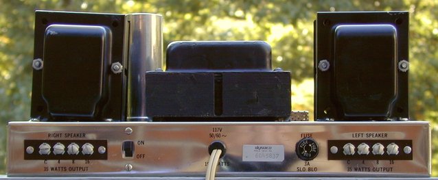
     At first glance, it looks like every other Stereo 70 you've probably seen.  But by 1970, "The Dyna Company" had been "Dynaco" for many years.  The 1970 version of the Stereo 70 reflected this fact by FINALLY labeling the right side of the chassis with the "Dynaco" stylized script.  You'll also notice that "Class II signal wiring may be used."  Right below that, you'll notice the familiar "UL" logo.  This little logo meant a LOT of work for Dynaco.  They had to "idiot-proof" the Stereo 70!  We'll take a look at the steps they took to get the assembled Stereo 70 to pass UL certification.  If you'll look closely at the left side, you'll notice the model number is "Stereo 70A."  This stands for "Stereo 70 - Assembled."  Also notice that the two octal sockets on the front panel are labeled "Biaset Socket", rather than "PAM-1 Power" or "Preamp Power", as in previous editions of the Stereo 70.  The old "Dynakit" foil label has been replaced with a brown plastic "Dynaco" label.  One more thing:  the only screws you see on the front panel hold the Stereo/Mono Switch in place.  Everything else is riveted!  Riveting the parts onto the chassis sped up assembly time a LOT!

     Here's a picture taken from a higher position:


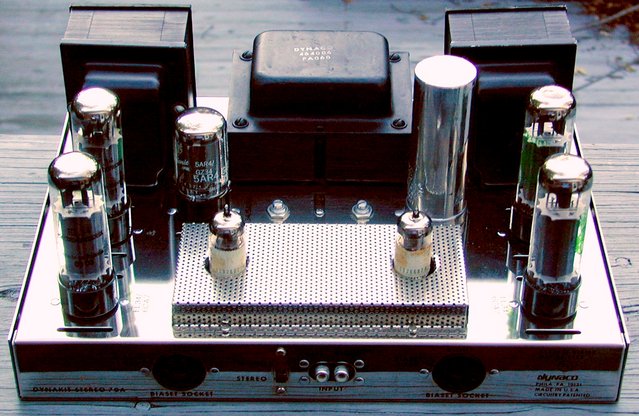
     I suppose you'd call it "Industrial Chic", but no matter what you call it, it certainly looks pretty to me!  From this vantage point, you can see the BIGGEST difference between a factory-wired Stereo 70 and a kit version:  The Driver Board Cover.  Let's take a look with the tube cage/cover removed:


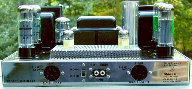
     In order to get the Stereo 70 to pass UL certification, Dynaco had to add that little perforated-metal cover over the Driver Board.  The reason is simple:  There's a LOT of High Voltage on the Driver Board!  The cover adds a layer of "idiot-proof" protection!  (It also keeps toddlers alive a LOT longer!)  These perforated covers originally appeared only on factory-wired units.  By the way, the tubes you see in the photo are as follows:  One NOS Mullard-manufactured, GE-branded 5AR4/GZ34, two NOS RCA black plate 7199 Driver Tubes (these particular tubes came from a trusted source in South America.  The import-duty tax stamps were added there.) and four factory-matched Electro-Harmonix EL34EH Output Tubes.  Here's a front-view with the cover removed:


     At this angle, you can see that there is a slight "list" to the Right Channel Output Transformer.  The mounting ears are just a *teensy* bit uneven.  Not a BIG deal, but it is interesting.

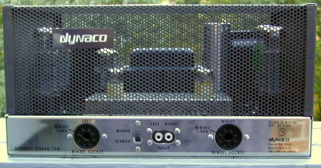
     The back of the Stereo 70 looks pretty "normal."  Here's a picture:


     You can really get a better view of the Right Channel Output Transformer here.  Quite a bit of tilt.  Still, it doesn't cause any electrical problems, just aesthetic ones.  Notice that the terminal strips are riveted to the chassis.  Also notice that a little foil label has been added.  Take a closer look:


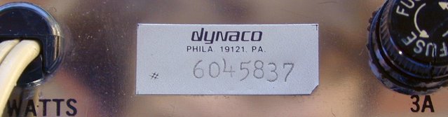
     This label shows the serial number of the unit, as well as the fact that this unit was "factory-wired" by Dynaco.  Also notice that a plastic strain-relief is used on the Power Cord, rather than a rubber grommet.  This is not exclusive to factory-wired units.  Dynaco went back-and-forth between grommets and strain-reliefs over the years.  One more item that bears mentioning is the Wattage Rating.  Earlier amplifiers had a 175 Watt power consumption rating.  Later units (like this one) show a 190 Watt power consumption rating.

     Just for grins, here's a picture of the bottom cover of this Stereo 70:


     That blue "tint" is the reflection of a clear blue sky.  While this bottom cover is certainly not *perfect*, it is pretty nice.  (The rubber feet had been removed prior to cleaning this cover.)  If you look carefully, you'll notice a scratch, as well as a small "pit" in the plating.  Otherwise, this one is nice and shiny!  But this bottom cover and the main chassis itself, are both different from the "normal" kit-built versions.  Once again, UL certification necessitated the change.

     In a kit-built Stereo 70, there are four screws that secure the bottom cover, and the tube cage/cover, to the chassis.  Remove those four screws and the main chassis will slide right off the bottom cover.  Underwriters Laboratories required Dynaco to find a method to keep the bottom cover secured to the main chassis even when the tube cage/cover was removed, since (according to UL), there are "no user serviceable components" inside the chassis.  Dynaco did this by using two very special screws in addition to the usual four cover screws.  Here's a picture of these "security screws":


     I doubt you have a screwdriver that'll easily take THESE babies out!  That's the whole idea!  The bottom cover for factory-wired units has a "dimple" in the middle of each side where these screws are located.  This dimple allows the bottom cover to be screwed to the main chassis without deforming the sides of the bottom cover.  In order to allow the tube cage/cover to be removed, it too was modified by notching the mounting strip to allow clearance for the bottom cover's "dimple" and security screws.  All this just to get UL certification?  Yep!

     OK, let's take a look "under the hood" of this animal.  Here's a picture of the underside of the main chassis:


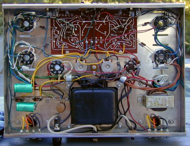
     Notice the "Inspection Stamp" between the bias supply and the fuse holder.  You'll only find this stamp on factory-wired units.  It is only stamped after the unit has passed final inspection. This particular amplifier should have NEVER been passed due to a "too close for comfort" condition at Pin 2 of the GZ34 socket.  The wire from the Power Transformer at this pin had an excessive amount of exposed conductor that was *almost* touching the ground lug on the tube socket.  As a matter of fact, SOMETIMES it DID touch the grounding lug.  Even a little vibration could make it contact the ground lug.  When that happened, it blew the fuse INSTANTLY.  But what happened at start-up was a LOT more interesting!

     When this wire made contact with the ground lug and you turned on the amplifier, everything would look normal until the rectifier started conducting.  Once it began delivering full B+ Voltage to Pin 8 (the cathode) of the GZ34, the full B+ Voltage was placed across the filament of the GZ34 and the fuse would blow!  It's the same symptom as a shorted can capacitor!  But in THIS case, the can capacitor was just fine.  This led the original owner of this amplifier to think that the Power Transformer was shorted.  Nope!  The Power Transformer is just fine too!  This one was a head-scratcher for awhile.  Every time I turned the chassis upside-down, there was enough "wiggle-room" to move the wire away from the ground lug!  I *finally* noticed it when I was pulling the GZ34 out of the amplifier while the amp was on the bench, upside-down.  Once that wire was redone, all was well in Stereo 70-land again!

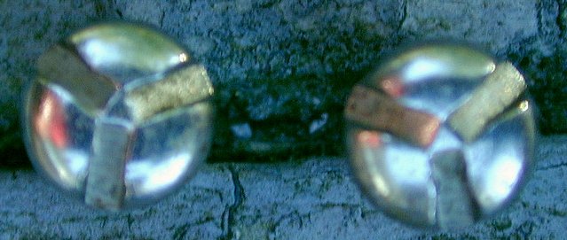
     After all these years, I'm afraid that finding a Stereo 70 chassis in *perfect* condition is largely a fantasy.  This amplifier is no exception.  But it is a LOT better than MOST of them.  Here's a picture of the worst pit on the chassis:


     And here's a shot of the second-worst pit:


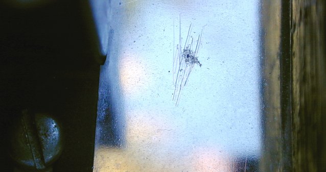
     The previous owner apparently thought that this pit was something that could be scraped off.  That's why there are scratches on the chassis over the pit.  Oops!

     By the way, this amplifier operates PERFECTLY!  It truly is an un-molested, correctly operating, factory-wired Dynaco Stereo 70 from 1970; still making BEAUTIFUL music after all these years!

Sincerely,

Bill Thomas

miklorsmith

That is one of the best posts of all time.   :thumb:

pbrstreetgang

  • Full Member
  • Posts: 604
Nice Bill! Any closeup of that arcing wire?

cryoparts

Wow!  And the hits just keep on coming. 

Peace,

Lee

Bill Thomas

  • Full Member
  • Posts: 424
     Thanks for the comments, guys!  Sorry that I forgot to snap a photo of the offending wire before I fixed it.  Rather than "re-create" the goof, I just decided to "tell it like it is" regarding this amplifier's one *teensy* little problem.  I'll try to do better next time.

Sincerely,

Bill Thomas

Rocket

Hi Bill

Quote
Wow!  And the hits just keep on coming.

I'll second that comment.

Regards

Rod

salb203

  • Jr. Member
  • Posts: 20
Awesome Bill ,
I also have a factory wired unit in my basement. I didn't play with it yet.

Keep em' coming.

Sal

2bigears

  cool unit,clean lines,neat work,love the power cord. :thumb:

KT

  • Jr. Member
  • Posts: 179
Bill,

Wow, I really love the image of the trees that's been screen printed onto the bottom cover of your amp. Did Dynaco offer screened images on the bottom plates of amps back then? Cool idea.

Funny thing is, though, when I look at the bottom plate of my ST-70, I see that Dynaco has screen printed an image of my own face onto the bottom of my amp. Crazy coincidence, huh? What are the chances that I would randomly end up with an amp that has my face on the bottom? And where did they get that image of my face to begin with? Weird.  :wink:

Seriously, though, that's one fine specimen you have there. I've never seen a finer ST-70. I guess it's just the nature of chroming that it doesn't last forever, but yours looks to be as good as it gets.

I had a ST-70 once that was totally beat to hell. Picked it up for $10 and planned on rebuilding it, but you know how that often doesn't happen. I ended up giving it away to a thrift store during a spring clean.

I'm impressed that your amp is totally stock. I have a ST-35 that was in great condition, no rust, just some minor corrosion on the stamped RCA's. Before I realized how cool having a stock unit is, I succumbed to audio upgrade fever and replaced some of the caps and resistors. Sounded better, but alas is no longer a stock unit.

Thanks for sharing your amp with us. Very cool.

Best,
KT


Bill Thomas

  • Full Member
  • Posts: 424
Hi, KT!

     Thanks for the VERY kind comments.  It is SO rare to find a totally original unit that is in such nice cosmetic and electrical condition.  This always begs the question, "Which is more desirable?  An absolutely bone-stock, un-tampered with, original unit?  Or one that has been completely rebuilt with all new components?"  Granted, the rebuilt unit will probably have a longer *future* life-span than an "original" unit, but, as in the old car hobby, "They're only *original* ONCE!"

     You can now build a brand new 1967 or 1968 Ford Mustang for yourself using all new parts.  You can build an all new 1969 Camaro as well.  There's not a thing wrong in doing so.  (Although you *may* have some difficulty getting a new VIN number, depending upon which State you live in.)  While you can go to GREAT lengths to make it look as "stock" as possible, it will NEVER be as valuable as an original, well-maintained "survivor."  Granted, it may COST more than an original to build one, but its true VALUE is always going to be MUCH less than one built by Ford in Dearborn, Metuchen or San Jose.

     Of course, I could always be wrong about this, but I don't *think* so.

Sincerely,

Bill Thomas

P.S.  If you'd like to take a look at a NEW 1967 Mustang "Sports Roof" that was built from all NEW parts, the following link will take you to an article in "Mustang Monthly" magazine with LOTS of pictures of the "blessed event!"  http://www.mustangmonthly.com/featuredvehicles/mump_0711_1967_mustang_replacement_body/index.html

     It's truly fascinating reading, but original?  No way!

Bill

Folsom

I think that think looks freaking sweet.

I still without question would modify it. Why would I do something like that to such a treasure? Well frankly it is no real treasure unless it has some use. There for why not use it? Oh wait it will sound three times as good with less than a hundred dollars worth of upgrades that do not steal the looks....

IEC socket for a real power cord. Ceramic fuse or bypass. Riken resistors put in where ever the very first resistors are used in signal path, then Kiwame or Vishay resistors for the rest (S102s if you want to spend some serious cash), seriously toss those dinosaurs. New capacitors (hell there is only what two of them) Blackgate BG N (with my special mod)/Obbligato or Mundorf Silver & Oil if you got the cash and depending on value and size. Put real RCA sockets and speaker binding posts on... Cardas for their black and copper/gold color only.

Hey why not just give it to me, I will do all those things :)

Bill Thomas

  • Full Member
  • Posts: 424
     Sure thing!  Just as soon as you convince the auctioneer at Barrett-Jackson to "give" you that 100 point Hemi 'cuda convertible so you can install those KEWL '59 Caddy tail lights on it!

     In the immortal words of one MUCH wiser than all of us:  "Father, forgive them!  For they know not what they do!"

     And by the way, how is Mrs. Stepford these days?

Bill

P.S.  If you REALLY want to do all those things to this unit, head over to the Trading Post and break out the checkbook.  Once you OWN it, you can do whatever you want with it.  I promise not to laugh (or cry)!

Bill

PeterCapo

  • Jr. Member
  • Posts: 38
Hey Bill!

Really enjoying the rebuild series and information you have been presenting.  They are an invaluable reference for the community.

One question: could you say more about the later designation that "Class II signal wiring may be used"?

Many thanks,
PeterCapo (the same "PeterCapo" from AA) 

Bill Thomas

  • Full Member
  • Posts: 424
Hi, Peter!

     "Class II Signal Wiring" is a designation by the N.F.P.A.  (The National Fire Protection Association),  These are the folks who issue the National Electrical Code.  This designation has NOTHING to do with audio signals, per se.  It is a class of wiring having to do with low-Voltage, low-current applications like doorbells and other low-Voltage control applications.  But "Class II Signal Wiring" also covers the type of wiring that may be used to run from the Amplifier to the Speakers.  This can be anything from doorbell wiring to telephone wiring (or almost anything else that has a conductor surrounded by an insulator).  There is also no need to run this wiring in conduit in commercial applications.  In other words, installation requirements are MUCH simpler than normal electrical wiring that delivers Line Voltage.  For example, it is strictly forbidden to run Lamp Cord carrying Line Voltage inside walls, but there was no problem doing so to connect speakers to the amplifier.

     The idea is that "Class II Signal Wiring" will not cause a fire IF someone were to hang a picture and run a nail through the wires and short them.  For complete information, refer the the current issue of the National Electrical Code.  You can *probably* find a copy to read at a local Public Library.  To be honest, I haven't looked at a copy in MANY years now, so this information could *easily* be outdated, but in 1970 it was necessary to include this "information" somewhere on the amplifier in order to obtain UL certification.

     Does that help?

Sincerely,

Bill Thomas

PeterCapo

  • Jr. Member
  • Posts: 38
Interesting, Bill.  Thank you!

Peter