Hi all,
I'm looking for some help biasing a Bryston 4B(reg) amplifier from the late 80's.
I'm somewhat experienced working with electronics, but new to working on amplifiers in general, and this is my first piece of Bryston equipment. I mostly own SAE gear.
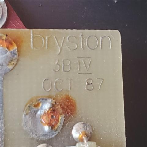
The main board is labelled "bryston 3B IV Oct 87"
I inherited this amplifier, and it was functioning perfectly - although the right channel was running a bit warmer than the left and had a bit higher DC offset (45mV compared to 20mV on the Left channel).
My plan was to re-cap the amp, and enjoy it for many years to come.
For some stupid reason I decided to just measure the bias level so I could compare it before and after re-capping to know if I needed to re-adjust it. BIG MISTAKE!!!!!
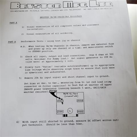
Initially I was using this document that I found on the internet, but I'm beginning to think it is from an older model than mine.
I recently found these instructions for the 4B SST, and I'm thinking they might be more applicable to my model (at least in respect to the test points):
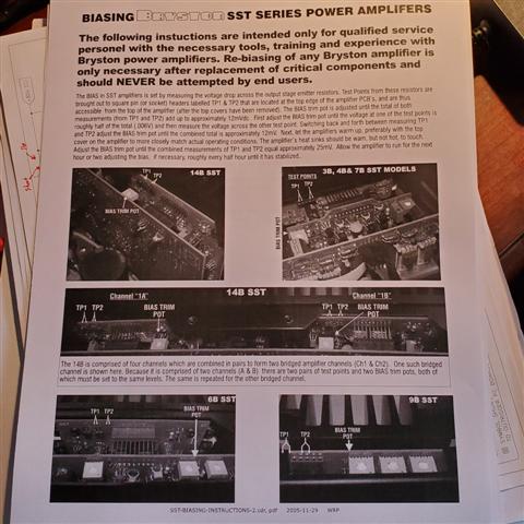
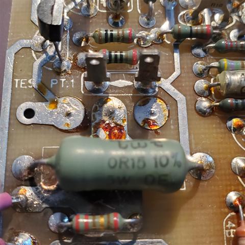
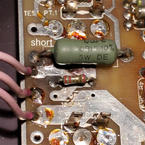
My question is, am I supposed to be measuring the voltage drop between the 2 metal posts adjacent to each of the test point labels "Test Point 1 & Test Point 2"? Should I set the bias for each Test Point to 6mV - giving a total or 12 mV for the two test points as in the SST instructions?
As far as I can tell these posts are connected to either end of the large green power resistors just below them, so this would give the voltage drop across the resistor.
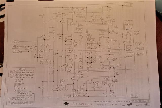
Also, I'm having great difficulties finding schematics and a board parts layout diagram for my model. The closest schematic I have been able to find is this one labelled January 12, 88, but its not exactly the same as mine. For example my trimpot is labelled 2K2 on the board (not 1K as in the schematic), and the transistor connected to the wiper is a 2N5550 (not a 2N5210 as indicated in the schematic). Also, mine doesn't have a protection relay as indicated in the schematic. I realize there are many revisions of the 4B design, but I'm wondering if there are schematics for my version.
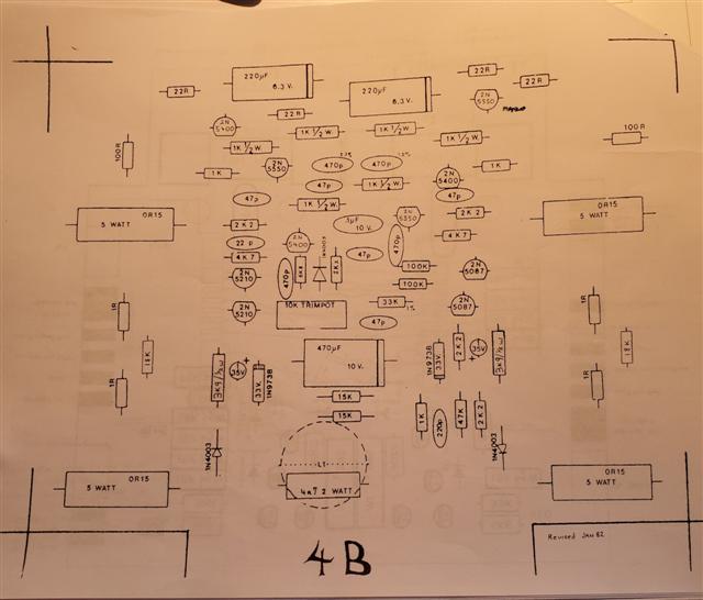
The only board layout I have been able to find is this one, but there are many differences to my board, and I think this is a much earlier version. It makes it very difficult to orient myself to trouble shoot the boards with so many of the same transistors and identical mirror image versions of circuitry without a properly labelled parts diagram.
I understand that Bryston uses "matched pairs" of the complementary output transistors, but I'm not exactly sure which transistor is matched to which. I'm assuming the BR6521 and the BR6522 on positive rail of the main board are matched to the BR6522 and BR6521 respectively on the negative rail. I'm wondering if the two BR6522's on one "outrigger board" are matched to their counterpart BR6521's on the other outrigger board? Without a parts location diagram there seems to be no way of knowing which transistor is which on the outriggers - and I'm not sure which 2 transistors forms a pair for matching purposes .
I apologize for the long rambling post, but I can't seem to get a response from technical support at Bryston, and I don't want to bugger anything up any more than I already have! Unfortunately, when I was trying to "just measure" the bias of the left channel, I accidentally shorted the power resistor lead on the +80V rail to the "test pad running beneath the 5 watt OR15 emitter resistor" as per the instructions in the above manual which took out at least 4 of the output power transistors!!!

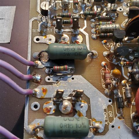
Here's a picture of the blown outputs. I think the rest of the outputs test good, but i'm guessing I will need to replace them all anyways since it took out one half of every pair as far as I can tell. Probably can't mix replacement pairs with original pairs anyways. From the sound of things it's going to be quite difficult to get replacement transistors as it is! Here's a picture of the transistors which are definitely shorted (in blue):
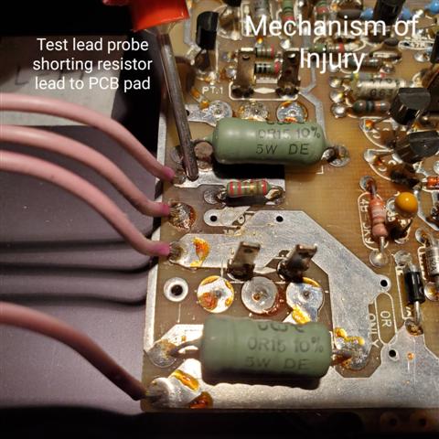
DMM test probe shorting resistor lead to PCB trace beneath it
Divot taken out of the trace by the arc! Relatively minor damage to PCB.
All traces are intact
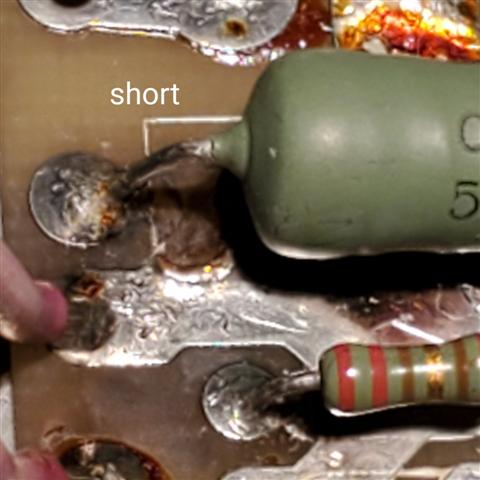
Close up of divot.
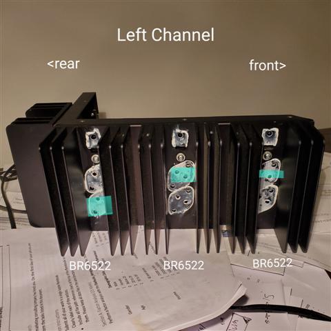
Shorted transistors (in blue)
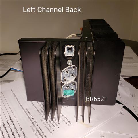
Shorted transistors (in blue)
I have thoroughly tested the boards passively (un-powered) with a DMM, and all the transistors, resistors, diodes, and capacitors seem to be ok (as far as I can tell, but I certainly can't be sure). Luckily I have a perfectly working right channel and was able to compare all readings when testing the transistors & resistors with my DMM. I checked the caps with my ESR meter and they are essentially unchanged from readings I took immediately prior to the short. The main fuse (outside) for the left channel is blown, but the internal fuse on the backboard is intact.
My thoughts are to hopefully replace all of the output transistors on the Left channel with new matched pairs (if I can get them). I gather that I will also need to replace the trimmer pot with a bourns multi-turn trim potentiometer to safely bias the amp.
My plan is once the parts are replaced, and with the trim pot set to its lowest bias setting - to power up the amp with a current limited DC power supply at 5 volts - and slowly increase to 20 volts if current draw is not excessive. If all goes well, I would then try to bias the amp mostly to see if the bias circuit is functional. If it biases ok, I would remove the bias setting, and then try it on AC with a dim bulb tester +/- variac and try to bias it. If that works, I would cross my fingers and bring it up on full AC.
I would love to power it up on DC first without the output transistors installed to see if there are any problems with the board, but I'm not sure if this is advisable, or even possible. I wouldn't really be able to test the bias circuitry without the power transistors installed anyway, so it would probably be pointless. Is there a better way to test the board without risking all the new outputs?
I thank you all in advance for any help that you can offer me to getting this beautiful amplifier working again
cheers
Amnesia