X-SLS Amateur Build

0 Members and 2 Guests are viewing this topic. Read 12432 times.

jonsk2514

Re: X-SLS Amateur Build
« Reply #20 on: 22 Apr 2023, 06:34 pm »
As I noted the cutout in each brace has the corners rounded.  This was done with a 3/8” quarter round.  Then I made a small bevel on the braces on the corner that matches with the glued back to side corner where glue extruded while being clamped and then hardened.  The bevel on the braces precluded the need to chip out the extruded and hardened, which allows the brace to fit in unimpeded.


Next is dry fitting the braces to the cabinets.  This is where they become custom fit to the cabinets.


This was done with the un-glued side clamped in place to get the width right and then with the front clamped in place along with that side.  Clearance with the top is a little harder to judge as the braces can’t be seen, so I just look for the top fitting flush with the sides, top and bottom.

It also turns out that the braces were slightly out of square.  Squaring them was easily accomplished along with the sizing of the braces.

I glued the braces using TiteBond Quick and Thick glue.  This glue is designed to fill small gaps, which will exist with these braces as the butt joints all of the way around them.


I use strapping film to protect the front panel from being glued by any extruded glue.


The unglued side is also protected from extruded glue with strapping film.

And then clamps, clamps, clamps at each brace to make sure they are each pressed into place.


The half braces take a little more effort.


It is first put into place with glue.

The it is clamped onto place.


The silver clamps are adjustable Harbor Freight welding clamps that worked well in this case with a little help with a piece of 2x4.

The sides are clumped with a parallel clamp to ensure the sides are pressed in.

jonsk2514

Re: X-SLS Amateur Build
« Reply #21 on: 30 Apr 2023, 07:34 pm »
It is crazy that glueing on one side has taken as many or more clamps as any other step in this whole build.  But it is easy to see why.


I should have taken a picture of how the glue was laid in, but I failed  :P  I used the Original Titebond glue on the 3 edges being joined with the top, bottom and back panels.  I used Titebond Quick & Thick on the edge of each of the braces.  The Quick and Thick will bridge any gaps between the braces and the side.  With the side lightly clamped in place the front panel was put in with the strapping film to ensure it is not inadvertently glued in.  Including the front is necessary to ensure the side panel is appropriately pressed into place on the back panel and to ensure the resulting width, when the glue sets, will allow the front to fit later on.

There are clamps side to side and front to back at each braces as well as at the ends.  There are end to end pipe clamps.  A mistake I made was losing track of where I placed the clamps and missed placing one on the side panel at the corner of the front panel and the top panel.  This meant that the side wasn’t pressed into the top as well as I would have liked.  But it will be okay.

Here are the side and back to top braces being glued in places.  I again used the Titebond Quick & Thick to bond these in place, as I did in the X-LS build.  I could have PL Max, as other have done.  Not sure if there is any real difference in this application.  I just like that the Titebond is specifically made for wood.


I did glue these braces into the correct end.  The cabinets are upside down to facilitate the glueing process.  And the brace is actually straight across  :eyebrows:

Glueing the front panel on is close at hand, so it is time to be thinking where to put the crossover board. In all honesty, this speaker is tight inside.  There are more parts to the crossover than will fit on the back wall of the speaker, without having to make a stacked sections of the crossover.  The plan is to mount the crossover on side wall.  This way it will be long enough to fit all of the parts.


corndog71

  • Full Member
  • Posts: 1672
  • Some people call me Rob.
Re: X-SLS Amateur Build
« Reply #22 on: 30 Apr 2023, 07:49 pm »
You can tighten things up a bit.


jonsk2514

Re: X-SLS Amateur Build
« Reply #23 on: 1 May 2023, 05:24 pm »
Nicely done  :thumb:

Thanks for sharing.

I thought about doing that but wasn't sure how to twist the wires together within that space as Danny has shown in his video. 

It looks like you have wound or wrapped one wire around another wire, instead of actually twisting them together.  Did I get that right?  :scratch:  If that works okey, then I’ll be able to do that.

corndog71

  • Full Member
  • Posts: 1672
  • Some people call me Rob.
Re: X-SLS Amateur Build
« Reply #24 on: 2 May 2023, 12:04 am »
Nicely done  :thumb:

Thanks for sharing.

I thought about doing that but wasn't sure how to twist the wires together within that space as Danny has shown in his video. 

It looks like you have wound or wrapped one wire around another wire, instead of actually twisting them together.  Did I get that right?  :scratch:  If that works okey, then I’ll be able to do that.

The key is a good physical connection before soldering.  As long as things are tight you don’t have to go crazy with twisting wires.  And then anchor the crossover to a small board with zip ties.

jonsk2514

Re: X-SLS Amateur Build
« Reply #25 on: 2 May 2023, 04:11 pm »
I gave the crossover layout a second try and was able to compact the size of it similar to the above posted by Corndog71.


Ignore the board it is on except for the outline which represents the available space at the back of the speaker where it will be accessible through the hole for the bass driver.

Basically the negative will be through the center of this cluster and the positives to the drivers come off the left and right sides.  The bass circuit is simple.  The input to the bass coil will be at the bottom and the output to the driver is at the top left, with the Cap connecting that to the negative.  The tweeter circuit is more complex, but the Caps and resistors stacks well, with the input to this circuit being to the left side of the bottom resistor (green).  From there back and forth such that the output to the tweeter driver is out the right side, with a resistor back to the negative.

As can be seen, no wires are connected.  But based on the above comment, it will be easy to make good connections between the wires before soldering.  From there, the section can be arranged on a board and zip tied in place.  The “blue stuff” is a non-oily mounting putty that I plan to use between parts to keep them from having a chance for buzzing or otherwise.

maty

Re: X-SLS Amateur Build
« Reply #26 on: 2 May 2023, 05:14 pm »
The tiny red capacitor (bypass) has me intrigued, what brand is it?

Audyn CAP Q4 MKP Polypropylene Capacitors 400V 5%


Hobbsmeerkat

  • Industry Participant
  • Posts: 2545
Re: X-SLS Amateur Build
« Reply #27 on: 2 May 2023, 07:13 pm »
Its a 0.1uF JB JPX cap.
It's the replacement for the Gen 2 Sonicap bypass we used to offer on our base level kits.
They're quiet nice for their price.

maty

Re: X-SLS Amateur Build
« Reply #28 on: 2 May 2023, 07:16 pm »
Thank you very much!

maty

Re: X-SLS Amateur Build
« Reply #29 on: 2 May 2023, 07:29 pm »
I think you will be interested. We know that the human ear is insensitive to distortion up to a few hundred Hz -> it makes sense to use laminated inductors in low-pass filters ONLY at frequencies < 400 Hz (approx.)

QAcoustics Concept 500, White paper, page 15


jonsk2514

Re: X-SLS Amateur Build
« Reply #30 on: 10 May 2023, 02:06 pm »
Still working on the build.  Making posts has been lagging though. 

As shown in my previous post, I was able to come up with a more compact arrangement. I like this better and it will mount in the back of the cabinet.

The tweeter circuit is the most complex with the most parts, so I broke it down into sections and made the connections in steps.  The first was to make connections between paralleled parts.


Then these parts were connected together.


The 180 deg bends were done after twisting the wires together.

Lastly the coil to negative and the resister to negative were connected.  The resistor to negative is on top of the  upper cap and, even though it looks to cross close to the connection below it, it is actually a ways away from it.  The actual connection of this resistor is to the right end of the upper cap.


As noted below the blue stuff is mounting putty that holds the parts together and will keep them from vibrating against each other.

The bass circuit is much more simple with only one connection between the the coil and cap.  This was done by clearing off some varnish from the coil wire.  The connection was made a little ways from the end so the end can be used to connect to the speaker wire.

Next - Soldering.
Really it is not very hard.

Tyson

  • Full Member
  • Posts: 11113
  • Audio - It's all a big fake.
Re: X-SLS Amateur Build
« Reply #31 on: 10 May 2023, 04:11 pm »
I like your work style - patient and thorough.

jonsk2514

Re: X-SLS Amateur Build
« Reply #32 on: 25 May 2023, 08:43 pm »
I like your work style - patient and thorough.

Thanks.  :thumb:

Once again other things have come up that have delayed my progress.

One of which was the failure of the power wire to the motor on my drill press.  No damage other than the plug broke when I tried to unplug it.  Time to fix it as it is needed for several of the next steps in this build.  But as with all projects I do, one thing tends to lead to another.  I had to take the motor off to fix the wire, so I thought I would replace the motor with a slightly newer and more powerful one I have.  I got that one all wired up and re-did the mounting as that was different.  Fired it up…   :shake:  Oh Crap! It rotates in the wrong direction…. I feel like  :banghead:  Back to the old motor.   This, too, required the mounting to be re-done in order to align the new pulling I put on it with the other pulley.  Then the switch fell apart when I tried to put the wires on it…  :bawl:  Well, it is all back together now, running well and has been put it to good use.

I made the mounting boards for the crossovers.  As with my past efforts, these are made from 3/16-ish lauan cut to fit on the back panel between the braces and inline with the bass driver.  These will be mounted on 1-1/8” high blocks so No-Rez can be installed beneath them.  The newly refurbished drill press made quick work of making holes for the crossover tie downs and in the mounting blocks.


Hopefully progress will proceed with some regularity now…  :?  We’ll see.  Time to start cutting holes for drivers and binding posts.

Yes, binding posts.  Tube connectors would be lost on the system this will be going into. :roll:  And don’t even ask about the speaker wire I am currently using.   :no_speak:

But I did go through and replace all of the magnetic parts with non magnetic brass parts as I did for my past progects.


Replacement parts


jonsk2514

Re: X-SLS Amateur Build
« Reply #33 on: 3 Jun 2023, 09:12 pm »
A little shellac on the crossover boards.


I know, doesn’t mean anything inside of the speaker, but I know what it looks like and it makes the board a little easier to handle.  Just to be sure… 2 layers of shellac…  :green:

Components zip-tied to the board.


And then test fit in its cabinet.


There is space around the board and the cabinet sides and braces.  One thing to consider will be contact between the wires and the braces that might cause unwanted noise with any vibration.

Once all of the required holes are cut, the wires can be sized and fit.

jonsk2514

Re: X-SLS Amateur Build
« Reply #34 on: 8 Jun 2023, 03:47 pm »
I concluded that at this point I only needed to put the hole into the back panel for binding post.  The plans call for a 3.525” dia by 1/8” deep countersink, and a 2.5” dia through hole.  All of my hole cuts are made with the circle cutter attachment on the plunge router base.


The countersink was made with a 3/4” dia bit with the center pin on the circle jig set for a 3-1/16” dia cut.  Ok a little confusing, but the circle jig is set up for a 1/4” bit.  A bit larger than 1/4” requires a smaller dia setting and a bit smaller than 1/4” requires a larger setting than the actual desired cut.  Hope that makes some sense.

The through hole is made with a 1/8” bit with the circle jig center pin set at 2-9/16”.  Yup, this will result in a 2-7/16” dia hole, a 1/16” smaller than the called for 2.5” dia.  I found in my other builds this made for a better fit with the binding posts.

First a practice cut.


This came out good, so the actual hole cut in the cabinet.


I am not sure if the bits are getting dull or the MDF I bought this time is not as high a quality as before, or both, but I am seeing more fraying than I have seen in my past builds.   I expect this will make little difference in the use of this speakers, but it did create more cleanup work.  The rough edge seen at the bottom of the hole is a result of removing the plug.  I intentionally did not cut all the way through when making the hole cut.  This was done to keep the plug (which is holding the center pin) from moving while making the hole cut.  If I made the cut all of the way through, then the plug tends to move which causes the bit to cut where it is unwanted.  The plug is removed by pushing it from the uncut side, causing the material on the plug to tear.  If the plug is pushed from the cut side, the material will tear from the panel, damaging the panel.

With the cleanup done….


With the binding post hole made, it was easy to have the leads from there to the crossover be sized so they hange out with enough length to allow the connection to the binding post be made.

Soldering the power leads was pretty straight forward.  The negative lead passes through the center of the crossover.  The positive lead from the binding posts also comes to the center of the board, but only to the edge to connect to the positive (input?) sides of the tweeter and bass circuits.  There are 3 connections to the negative lead plus a “Y” split to the drivers.  There are separate positive leads to the tweeter and bass drivers.


I did zip tie these leads to the board to ensue they didn’t pull on the much thinner component wires.  In some places I used the zip ties on the large coil as anchor points.  I also added “U” loops in these smaller wires to act as strain reliefs if they were to be pulled on.

All of the connection were covered with heat shrink tubing.  Where I thought the heat gun would unnecessarily heat some of the components, those were protected with a bit of aluminum foil.


jonsk2514

Re: X-SLS Amateur Build
« Reply #35 on: 13 Jun 2023, 08:48 pm »
I should have mentioned that I was able to resolve an issue I was having with my soldering iron.  In my past projects I migrated from a 24w  to a 45w pencil type soldering iron.  This was needed in order to solder the junction of several heavy gauge wires or a bunch of wires.  However, in doing so, I found that after a few minutes of running the 45w iron would overheat and oxidize the solder on the tip, which then needed to be cleaned off in order to make good follow on joints.  My solution…


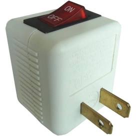
A very simple solution.  This way I could have the iron on when I needed it, and easily turn it off when done making a solder joint.  Worked great  And way better than some of my well over-thought ideas.  Yup, a lot of really complicated and/or more expensive solutions went through my head…  :duh:

As for the heat shrink tubing, my old Black and Decker heat gun has started spitting out insulation.  So, I was game for trying something new, keeping in mind how much I hate cords and hoses….


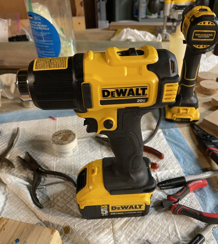
I love the idea of not having a cord that inevitably will knock something off the work bench.  And, nope, this will not peel the paint off a wall.  But it works great on heat shrink tubing…  :thumb:  And don’t get me wrong, Dewalt makes some nice things that I really like, but they also make some clunkers.  The drill in the background is an example…. How could they get the chuck and variable speed so wrong :cuss:

Now their little 20v router… I am a fan, as you may have guessed from my earlier posts.  Yes it can get over loaded with a large bit, like the 3/4” bit I used to make the recess for the binding posts and for the tweeter, but that is easy to work around.  Otherwise I find it works really well and there is no cord to deal with  :dance:  I was even able to rig a vacuum line from the ceiling for dust collection, which kept it from getting in the way.

As it was, it made quick work of holes in the front panel for the drivers and port…


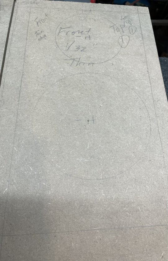
To start, I did a layout of each of the holes.  And lo and behold, I caught a mistake on the location of the hole centers on one panel.  Yup, just one.  Why, just one?  Don’t know.   Hmmmmm for one panel 8.5” divided by 2 = 4.25 and the other it = 4”.  :scratch:  I did them both at the same time, but long before this.  So, there were multiple reasons for making the over check.  Measure 2, 3, 4 times…. Cut once…   :lol:
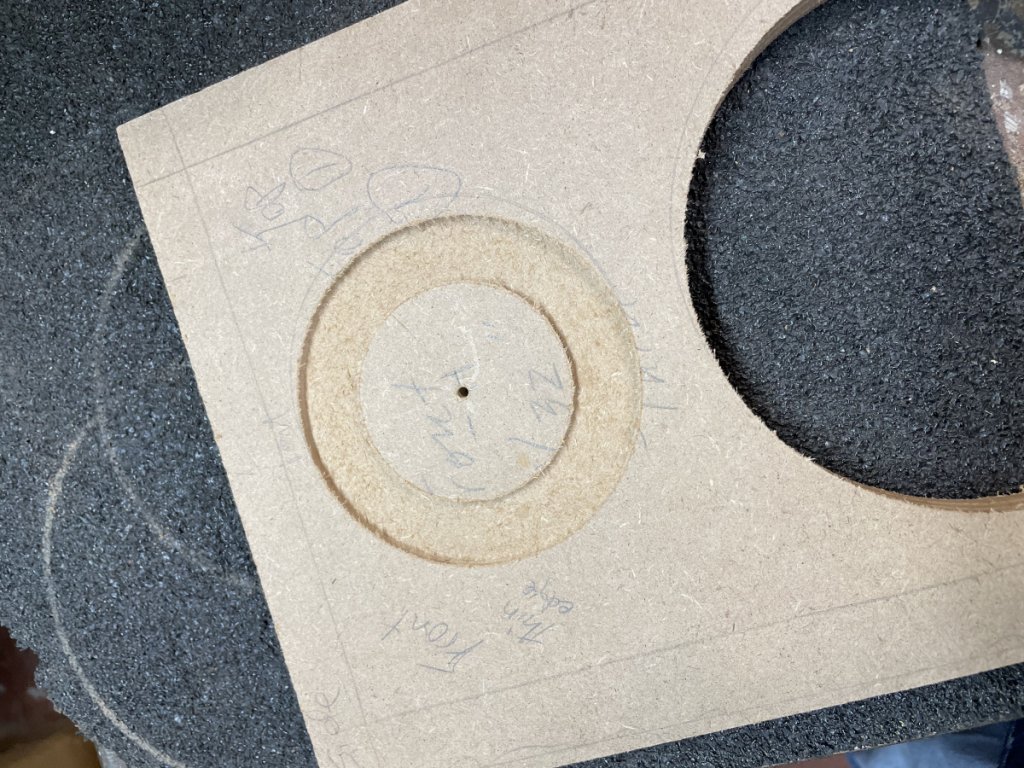
The hole cut for the tweeter is a 2 step process for me.  First is to cut the recess, then the through cut.  The recess is 3-15/16” dia and 1/8” 0.18” (or 3/16”) deep.  The center setting on the hole jig is 3-7/16” with the 3/4” dia cutter.  The  through hole is 3-1/8” dia made with 1/8” dia up cut spiral bit with a center setting of 3-1/4” on the hole jig.


The 2 remaining holes to be made are for the bass driver and the port.  The port is a 2” hole made with the 1/8” dia bit with the jig center set for 2-1/8”.  The base driver hole is called for 5-3/4” dia, however I like the fit with the hole cut at 5-11/16”.  This was done with the 1/8” dia bit with the jig center set for 5-13/16”.  Remember that the jig settings here are set to account for the smaller bit size than the 1/4” dia bit the jig is design for.  Again, I hope that makes sense.


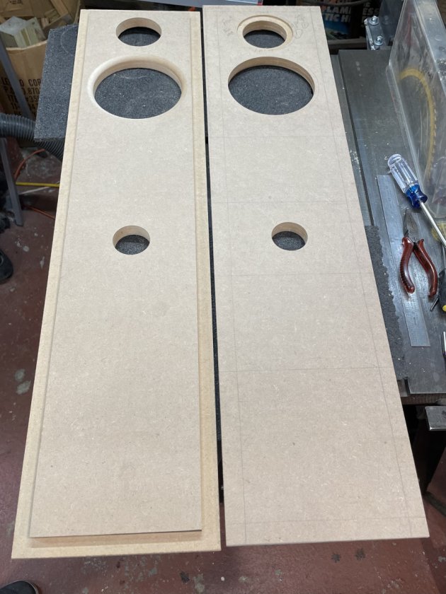
Here are the 2 front panels, one showing the back side and one the front side.  I added a 3/8” round over to the back side of the bass driver openings, the same as is called out for the X-LS cabinet.  The reliefs for the tweeter driver’s wiring tabs still need to be cut in, otherwise they are ready for being glued in.

Yes, I know, the ports belong in the back.  However, that does not work for the room these are going into.  So, the same as I made the X-MTMs, the ports are in the front.   I will say, if I am missing anything by having the ports on the front of the X-MTMs, I can’t tell.  They sound fantastic.  I expect these, too, will sound fantastic with the ports in front.

One other thing.  Notice the recycled rubber mats I am working on.  These were “sticky” enough with the MDF to hold the pieces in place, prevent them from moving/sliding, without any clamps.  That was such a bonus to not have to deal with clamps being in the way while making the hole cuts.  Further bonus was that they caused no damage to the router bits when they went through the back side of the piece being worked on.   :thumb:
« Last Edit: 15 Jun 2023, 03:10 pm by jonsk2514 »

Tyson

  • Full Member
  • Posts: 11113
  • Audio - It's all a big fake.
Re: X-SLS Amateur Build
« Reply #36 on: 13 Jun 2023, 09:18 pm »
Ports on the front are perfectly fine.

jonsk2514

Re: X-SLS Amateur Build
« Reply #37 on: 16 Jun 2023, 12:42 pm »
Another mistake…. :oops:

I never said.that I was good at this…

And I hope that others learn from my mistakes, because I surely have not.  :cry:

First I mis-marked the centers for the holes in the front panel.  One would think after that I would have been extra careful with cutting those holes.  But no…  :duh:  For some reason my brain told my hand to set the routor’s plunge depth for the tweeter recess to 1/8” instead of the called out 0.18 (or, 3/16” as I found worked well).  This, after I checked my practice piece which had the correct dimension.  A real eye-brain-hand issue.  :scratch:  Good I did a test fit of the drivers before glueing the fronts to the rest of the cabinets.  The fix would have been a bit more difficult later in the build.

As it was, the fix necessitated re-establishing a physical center to the cutout for the tweeter so I could use the router to make the recess deeper.  This entailed fitting a plug to the hole for the tweeter.

I started with a plug dropout from making the bass driver holes.  Using the hole cutting jig for the router I set the center pin to cut a hole that would result in a plug that was 3-1/8”, same as the opening for the tweeter.  I did a quick shallow cut to ensure I had come up with the correct center pin setting.


Yup…

After that, I made a recess cut to the correct dimension.


I did this as I thought it would be good to have that out of the way when making the cut on the font panel.

Then I cut out the plug


The plug was too much of a perfect (that is “snug”) fit


This required a bit of hand sanding to get a sung, slip fit in the hole for the tweeter


A slight difference can be seen between the recess cut on the plug vs the panel.  Just enough to make the tweeter sit proud.  And yes that is a little “oops” in cutting the reliefs for the connecter on the tweeters, which we won’t talk about.  :oops:

With the re-establish center in place, it was a simple matter to cut the recess to the correct dimension.


Phew - Fixed


Now back to moving forward…  :roll:

jonsk2514

Re: X-SLS Amateur Build
« Reply #38 on: 24 Jun 2023, 03:34 pm »
One reason I put so much detail into my threads is so I can go back to see what I did before and not reinvent the wheel.  I went back to my X-MTM build to see how I did the bases for those.  Well, not enough detail.  But a tidbit I did put in was that I should have done the mounts for the bases before installing the drivers.  I was thinking of doing that for these cabinets.

The width of these cabinets is the same as the X-MTMs, but the length is much shorter.  I liked how the base for the MTMs turned out so I used that as the starting point.  It was a simple matter of cutting about 4” of length out of the middle of the pattern I had and then touching up the curve of the sides.


The base is made from 3/4” sanded plywood.  It will take a bit of finish sanding to get them ready for painting, but it is not critical as the paint will be slightly textured as it was on the MTM bases. The cabinet fits on the base from left (back) to right (front) in this picture.

As I did on the MTMs, the 1/4-20 leveling screws are just threaded into the plywood.  The hole was drilled slightly smaller than 1/4” so treads could be formed in the wood.  Thread forming was done simply with a waxed threaded rod run in and out of the hole a few times with a drill.  Here it would have been a good idea to have chamfered the edges of the holes to keep the wood from splitting out as the threaded rod went through.  Lesson for the next time.

The ends of the leveling screws will be capped with nylon acorn nuts to protect the floor.  The base will be attached to the cabinet with black hex drive pan head screws into 3/4” threaded inserts in the MDF.

The mounting holes were match drilled from the base into the cabinet bottom.  I drilled a hole through a piece of metal rectangular tube on the drill press and used that as a guide to make sure I drilled the holes straight… I need a bit of help these days… :roll:


The hole guide worked well, but my estimate for the size hole to drill was way off, too small, and the first insert I installed did a good job of blowing out the MDF around the edges of the hole…  :slap:  This is an item I wish I had included in the X-MTM thread… The hole needs to be 3/8”.  There.  Recorded.

I also found that a stepped drill bit was good for opening up the hole at the edge a slze larger than 3/8” to keep the edge from flaring out when the insert is installed.

The corners of the bases need to be rounded and the bases need to be painted.  But this part is done.


jonsk2514

Re: X-SLS Amateur Build
« Reply #39 on: 25 Jun 2023, 06:05 pm »
A few notes about working with this MDF that seem to be different from that which I used to make the X-MTMs.   The X-MTM build was long enough ago I don’t remember all of the details.  But, I don’t remember having the issues I had this time with drilling holes in it and installing the thread inserts.  Even with the correct size holes the inserts flared the corners of the holes more than I remember occurring on the X-MTMs.  Even drilling the holes seemed to be more difficult and they are the same bits, which don’t get used a lot, so I doubt they are dull.

I understand that there are other brands of MDF out there than what I used.   I did get mine from a big box store; same one as before.  So I expected the same as before or close, right or wrong assumption.  Maybe another brand would have been different, but I gots what I gots….  :|

I needed to get creative to get around the issues I was having…


Drilling the hole was a surprise as it was more difficult than I expect.  I have 2 different drill bits (in the picture). One with a common point and the other with a dual point (hope that is a good name for it).  I find the dual point bits cut too aggressively when using a hand drill.  As I was hand drilling, I made the first hole in the MDF with the single point drill.  It took a lot more pressure on the drill than I was expecting to use to get the bit to cut.  When it broke through the other side it pushed/ripped out a lot of material.  For the second hole i used the dual point drill.  The more aggressive cut worked well in this case.

These initial holes were somewhat large pilot holes that needed to be enlarged to 3/8” for the inserts.  For this I used the single point drills and even this turned out to be aggressive.  Hmmmm  :dunno:  Could it be that it was the actual drill bit point pushing into the MDF that was preventing the bit from getting a good bite?

After sizing the hole, I used a step drill bit to enlarge both ends of the hole to the next size beyond 3/8”.  This is just a bit from Harbor Freight; any would do.  It worked well in the MDF and was easy to control the depth of cut which was a little over 1/8”.  As shown, I needed to get a bit creative with a right angle drive and extension in order to work on the end of the holes inside the cabinet…  :green:

The results of the insert installation on the second cabinet were much better than on the first.  There was minimal flaring of the corners, which was what I was hoping to achieve.  This issue really didn’t affect anything, and no one will see it.  But I wanted to see if it could be done better…  :roll: 


Much better…