I'd like to get your input on product development options

0 Members and 1 Guest are viewing this topic. Read 13464 times.

justubes

  • Jr. Member
  • Posts: 35
Re: I'd like to get your input on product development options
« Reply #40 on: 4 May 2015, 03:46 am »
Therr are 2 lm324 per board and the pins are not facing the ldrs.

You have specified channels 2 and 3  in each lm324 , which are both rows closest to the ldrs
Please clarify.

Also is there any testing to be done or if it sound worst just reconnect the clipped pins.

I dont quite understand what a buffer with and with does for the signal or power.

Thanks

tortugaranger

  • Facilitator
  • Posts: 1752
  • Innovated passive & active preamp technology
    • Tortuga Audio
Re: I'd like to get your input on product development options
« Reply #41 on: 4 May 2015, 01:37 pm »
Therr are 2 lm324 per board and the pins are not facing the ldrs.

You have specified channels 2 and 3  in each lm324 , which are both rows closest to the ldrs
Please clarify.

Also is there any testing to be done or if it sound worst just reconnect the clipped pins.

I dont quite understand what a buffer with and with does for the signal or power.

Thanks

There are 4 LDRs - 1 series & 1 shunt per left/right channel. Each op amp serves a channel. One side of op amp serves the series LDR and the other side the shunt LDR.

While it remains unproven, I submit that bypassing the op amp buffer stage to each LDR may reduce the noise and thus improve  performance. I've had this on my "to try" list for some time but simply have not gotten around to it - too much other stuff to do. If  you're looking for a potential tweak - this is the one I recommend someone try and let us know what you think.

I don't know why but after the V2 design was set and production boards were made I noticed that there was way more noise on the buffer stage output than there should be. Said differently, there's far less noise on the input to the buffer stage than the output. We do add a 0.1 uF bypass to the output pin to help reduce this. So why not just bypass the buffer stage and see if there's a benefit? That's the proposed tweak. As to why we ran the control signal through a buffer stage at all? Let's just file that under "it seemed like the right thing to do at the time" and move on.

Worst case is you try this on your V2.1 board, there's not discernible benefit  and you've ruined a pair of 25 cent op amps for nothing - such is life. Best case scenario is you confirm a relatively easy tweak that improves the sound via noise reduction - hooray!

tortugaranger

  • Facilitator
  • Posts: 1752
  • Innovated passive & active preamp technology
    • Tortuga Audio
Re: I'd like to get your input on product development options
« Reply #42 on: 4 May 2015, 03:16 pm »
There are 4 LDRs - 1 series & 1 shunt per left/right channel. Each op amp serves a channel. One side of op amp serves the series LDR and the other side the shunt LDR.

While it remains unproven, I submit that bypassing the op amp buffer stage to each LDR may reduce the noise and thus improve  performance. I've had this on my "to try" list for some time but simply have not gotten around to it - too much other stuff to do. If  you're looking for a potential tweak - this is the one I recommend someone try and let us know what you think.

I don't know why but after the V2 design was set and production boards were made I noticed that there was way more noise on the buffer stage output than there should be. Said differently, there's far less noise on the input to the buffer stage than the output. We do add a 0.1 uF bypass to the output pin to help reduce this. So why not just bypass the buffer stage and see if there's a benefit? That's the proposed tweak. As to why we ran the control signal through a buffer stage at all? Let's just file that under "it seemed like the right thing to do at the time" and move on.

Worst case is you try this on your V2.1 board, there's not discernible benefit  and you've ruined a pair of 25 cent op amps for nothing - such is life. Best case scenario is you confirm a relatively easy tweak that improves the sound via noise reduction - hooray!


My curiosity couldn't stand it any longer so I just went ahead and tried this mod. Don't bother. I put a scope on it before/after and there was no change which is as it should be. I believe the noise issue I was seeing earlier had more to do with instrumentation ground loops than anything else. I made sure there were none this time and so no change. Save your op amp and don't try it. The good news is the noise on the control signal to the LDR's is down around +/- 5 mv which considering the regulator is on the order of +/- 10 mv is not all that surprising.

justubes

  • Jr. Member
  • Posts: 35
Re: I'd like to get your input on product development options
« Reply #43 on: 4 May 2015, 05:19 pm »
Thanks Morten,

i didn't stand a chance, quickest hand draws first. Thanks for the update so we shall leave it as it is.
Just wondering how the belleson reg turned out in your testing.

So the v2.1 ias it stands is as great as it can  :thumb:


tortugaranger

  • Facilitator
  • Posts: 1752
  • Innovated passive & active preamp technology
    • Tortuga Audio
Re: I'd like to get your input on product development options
« Reply #44 on: 17 May 2015, 09:00 pm »
While still very much early stage, version 3 (V3) of our LDR preamp controller system is taking shape.

A key departure with earlier versions (V0, V1, V2 & V2.1) is the V3 will physically divide the preamp controller into 2 different board types; the Controller Board ("CB") and the LDR Board ("LDRB"). The CB will do most of the work and is the "smart" board that communicates with both the LDRB as well as the outside world (i.e. the user). The LDRB will contain the actual LDRs for one left/right single-ended stereo channel. The LDRB will simply respond to commands from the CB. The CB and the LDRB will communicate over a simple I2C network.

By breaking this preamp controller system into 2 board types it will be much easier and much less costly to implement multi-channel systems. For example a balanced audio preamp would require only 1 CB but 2 LDRBs. If you wanted to add additional stereo channels you would just add more LDRBs. This approach would definitely make bi or tri-amping more practical including multi-channel DAC attenuation.

As currently conceived, all power will come from the CB which would have separate digital and analog voltages which would be distributed to the LDRBs. Connections between the CB and one or more LDRBs would be via daisy chained 2x5 ribbon cable connectors so they could be physically arranged/distributed as desired.

Both board types will utilize mostly surface mount components which should make everything smaller yet there will still be various pin connectors to a host of external devices as before. At this point it appears we have eliminated the use of op amps entirely along with a good number of related resistors. Hopefully that won't change. Changing from 12 bit to more flexible 16 bit DAC/ADCs has helped simplify and further reduce total parts count while bumping up the overall accuracy of the controller which can only help improve sound quality. 

While nothing is set in stone yet, the V3 will likely have Bluetooth communications in addition to the existing IR/remote functionality which means it will be controllable via most iOS/Android phones via a custom control app.

The LDR/audio signal end of things is not going to change much from the V2/V2.1 except that the audio in/out of both channels will have optional isolation LDRs that will function as on/off switches in lieu of relays for isolating the LDRB during auto-calibration. If the LDRB is connected to multi-input switching devices these may not be required hence the reference to "optional". The auto-cal isolation relay will continue to be a conventional relay but is not in the signal path during normal operation (same as now).

The V3 is still quite a ways off and I'm not going to even begin to speculate on timing. Questions and comments welcome as always.

On a final note, I don't envision the V3 being something that existing owners of earlier V2/V2.1 systems should feel compelled to upgrade to because as things stand now I don't have any expectations that the V3 will improve on the overall sound performance - which is already quite amazing.  :thumb:


poseidonsvoice

  • Full Member
  • Posts: 4016
  • Science is not a democracy - Earl Geddes
    • 2 channel/7 channel setup
Re: I'd like to get your input on product development options
« Reply #45 on: 17 May 2015, 11:28 pm »
An audiophile/HT wet dream for sure! Keep at it Morten, I'll be one of your 1st customers...

Best,
Anand.

rajacat

  • Full Member
  • Posts: 3239
  • Washington State
Re: I'd like to get your input on product development options
« Reply #46 on: 28 May 2015, 07:28 pm »
Would it be possible to program a phase reversal switch into the software?

tortugaranger

  • Facilitator
  • Posts: 1752
  • Innovated passive & active preamp technology
    • Tortuga Audio
Re: I'd like to get your input on product development options
« Reply #47 on: 28 May 2015, 08:21 pm »
Would it be possible to program a phase reversal switch into the software?
This is the second inquiry on this topic today. Just got off a phone call about this for a balanced unit.

Phase reversal is relatively straight forward with balanced audio since you are already dealing with 2 signals, each 180 degrees out of phase with respect to each other. These are on pins 2 and 3 of XLR connectors. To reverse phase you can simply reverse their connection. I'm looking into how best to do this with our balanced units using the existing hardware. One approach is to connect a pair of inputs to 2 different input board channels with one channel wired "normal" (2 - 2, 3 - 3) and the other wired reversed (2 - 3, 3 - 2). By switching between these 2 inputs you are reversing the phases of the same input.

When it comes to single ended audio the only way I can think of to actually reveres the phase is to either run the inputs through inverted op amps or through transformers. This isn't something that can done with the stock hardware. You could run an input into two different inputs with one going through a transformer which would reverse its phase and the other connected normally. Then it would be a matter of simply switching inputs as to which phase sounds best.

If anyone else has other ideas or perspectives on this would love to hear your thoughts.

Cheers,
Morten

uraqt

  • Jr. Member
  • Posts: 8
Re: I'd like to get your input on product development options
« Reply #48 on: 21 Jun 2015, 12:18 am »
I like the V3 design... Keep allowing Apple remote for power and volume and I am in to upgrade my V1.2  : )

I used an Apple iPhone/iPad/usb charger for my power, what about adding usb for power too? Possibly you could drop the wall-wart?


Thanks and keep up the great work!!!

C

kernelbob

  • Full Member
  • Posts: 434
Re: I'd like to get your input on product development options
« Reply #49 on: 21 Jun 2015, 03:59 pm »
I'll fess up that I'm the guy who's been bending Morten's ear on the topic of absolute polarity reversal.  I'm currently relying on the DAC to handle that, but there are DACs that don't have that option or only via a switch on the front panel.  Having that feature on the preamp would also work on inputs from phono stages.

My request is for polarity control on at least one input, though Morten indicated that the architecture of the LDRxB could handle multiple inputs with polarity control.  Since I use a fully balanced system, DAC to power amps, the limitation of this control to balanced units is not an issue for me.  I would want the polarity control on the remote, since selecting the correct setting for each particular recording is best done from the listening position.  Also of importance is that the switch be easily and quickly made from the remote, not buried in a secondary menu level as is sometimes the case with DACs.  Apparently some manufacturers assume that a user would only need to choose a setting once when setting up the system, which is definitely not my experience.

Lastly, it would be useful to have some sort of indicator on the display.  Even a few pixels would be enough, on or off corresponding to the polarity selected.  Another thought is to use different brightness levels for the left and right volume settings with the left display brighter then the right and vice versa when polarity is inverted.  That wouldn't require differences in the display hardware.

As far as how to manage adding another control function to the Apple remote, my suggestion is to use the play/pause button for phase reversal.  I notice that when I want to mute the audio that I use the menu button.  It works just as quickly as the play/pause button and I've not heard any change in sound when bringing the audio back up from the "off" state.  It's my understanding that even when the menu button is activated that the LDRs are not fully turned off.  Perhaps Morten could illuminate (pardon the pun) the difference in the state of the LDRs between "off" via the menu button and "muted" via the play/pause button.

I realize there may be customers who would not be interested in polarity inversion.  Would it be possible to have a control function that would activate/deactivate it?  My suggestion is to use a long-press of the play/pause button to activate/deactivate polarity inversion control.  If the customer didn't want to use the feature, the play/pause control would work as it does today in the default configuration until activated.

My experience with implementations of polarity inversion control in the analog domain, such as a switch on a preamp, has been that when the inverted setting is activated, the signal often goes through additional switches and/or circuitry that compromises the sound compared to the non-inverted mode.  From discussions with Morten, this would not be the case with the Tortuga implementation.

Thanks again to Morten for his openness to customer feedback and suggestions.

Best,
Robert

tortugaranger

  • Facilitator
  • Posts: 1752
  • Innovated passive & active preamp technology
    • Tortuga Audio
Re: I'd like to get your input on product development options
« Reply #50 on: 21 Jun 2015, 06:31 pm »
I like the V3 design... Keep allowing Apple remote for power and volume and I am in to upgrade my V1.2  : )
I used an Apple iPhone/iPad/usb charger for my power, what about adding usb for power too? Possibly you could drop the wall-wart?
Thanks and keep up the great work!!!
C

The V3 design continues to evolve since the last post on the subject. We've done away with a separate controller board and are staying with the same concept as with the V2 where a single LDR board can serve as both master or slave based on flipping a jumper. The earlier idea of having 2 different board types added complexity while really not saving much in cost. The key difference between the V2 and this V3 prototype is the adoption of I2C networking which will allow for up to 16 separate stereo channels - way more than will likely ever be used. Meanwhile each board is self-contained so the board-to-board network interface remains a simple 2 wire daisy-chained serial connection.

Being a software driven system, there will inevitably be cause to upgrade the firmware. One challenge with multiple networked boards is we want to avoid having to update each board individually as is the case with our V2 design. With the V3 we want to only have to update the master firmware and then have the master automatically handle updating the firmware on any other slave boards present. That's all doable but we have yet to do the development work.

I've included a snapshot below of the current V3 layout. This will undoubtedly change as we refine the design but I think we'll be able to keep the board to roughly 2.5" x 2.7" as shown with most IC and discrete components being surface mount. That's literally 50% smaller than the V2 board. AND there's no secondary piggyback board as there is with the V2 so this will be a much lower profile board.

Those with an eagle eye and design experience will note 2 voltage regulators side by side labeled 7805 and 317. We don't intend to use either of these established regulators but instead are exploring the use of both our own as well as third party high performance discrete and semi-discrete drop-in regulators that use the same 3 terminal through-hole footprints as either of those regulators. Also, the V3 will definitely use separate digital and analog power.

Cheers,
Morten


rajacat

  • Full Member
  • Posts: 3239
  • Washington State
Re: I'd like to get your input on product development options
« Reply #51 on: 21 Jun 2015, 08:04 pm »
Has anybody tried using batteries for the power supply?

kernelbob

  • Full Member
  • Posts: 434
Re: I'd like to get your input on product development options
« Reply #52 on: 21 Jun 2015, 08:37 pm »
Re a battery power supply, I've purchased an Optima marine battery for that purpose.  It's way overkill for the current draw of my LDR1B, but if I ever need to jump a car or tractor, it will do the job.  I'm going to use a trickle charger connected to a remote controlled AC relay that I can turn off when I'm listening and on when I'm not.  I'd like to find a relay that can use the 12v trigger output of the LDR1B.  I need the trigger-on to turn off the relay and the trigger-off turning it on.  I think the LDR1B is a perfect candidate for battery power supply this since it uses a wall wort for DC power instead of the internal power supply conversion in the LDRxB.  I just need to salvage the input connector from another wall wort for a forgotten device from the past.  I just haven't gotten around to wiring up the battery since the LDR1B sounds so good as is.

rajacat

  • Full Member
  • Posts: 3239
  • Washington State
Re: I'd like to get your input on product development options
« Reply #53 on: 21 Jun 2015, 08:48 pm »
I agree the Tortuga sounds great as is but audionervosa creeps in just enough to be curious if off-the-grid power would make any difference. I will be looking forward to your experimenting with that Optima battery.

tortugaranger

  • Facilitator
  • Posts: 1752
  • Innovated passive & active preamp technology
    • Tortuga Audio
Re: I'd like to get your input on product development options
« Reply #54 on: 21 Jun 2015, 09:49 pm »
Has anybody tried using batteries for the power supply?

Funny you should mention it. This question of performance on battery has been burning a hole in my curiosity pocket for a while now. Especially since KernelBob went out and bought a big honk'n marine grade battery to try this on his LDR1B.

Yesterday I went out and bought a 10 AHr 12 V battery and have had it running on a Tortuga V2.1 board for the past 24 hours while turned on with dual displays. It went from 12.56 to 12.15 volts over that time period so plenty of capacity relative to load. Tied to a recharge circuit my guess is you could listen to music nonstop for a couple of days before you'd need to kick in recharge. That size battery fits inside the same enclosure as the LDR1B or LDR3.V2.

Today I spent some time taking measurements of the command signal to an LDR under various power supply scenarios. While not exhaustive or definitive I think the following findings are valid:

1) Most of the noise/hash in the control signals to the LDRs is a combination of the 5 V switch mode DC converter on the controller board plus the microcontroller. The DC converter runs somewhere above 100khz and the microcontroller runs at 4 MHz. The net of this is vey roughly +/- 10 millivolt noise way outside the audio band.

2) I saw no change in this whether I powered the board from a 12 V switch mode supply or from the 12 V battery. Keep in mind that the board uses both the raw 12 V supply as well as 5 V from an on board switch mode regular.

3) Next I removed the pricey on board 5 V DC switch mode regulator which has really good specs BTW and replaced it with a cheap (25 cent) LM7805 linear regulator and then ran the board off the battery. This cut the high frequency noise/hash by 50% to 5 millivolts. I suspect that the reduction was due to the elimination of the switch mode regulators switching noise up in the 100's of kHz.

All fine and good but did the battery plus cheap linear regulator help the performance? Honestly, I don't know. It sure sounded nice but then again....it always sounds nice!

Then I ran autocal with the battery/cheap linear regulator to see if anything changed with the reduced high frequency noise. It DID! Autocal ran smoother and faster. This was with the stock autocal op amp and not the upgrade. Autocal being a closed loop instrumentation circuit this makes general sense since signal noise will impact performance.

Too early to draw definitive conclusions but this suggests the unit would be happier with pure DC supply and no switch mode noise. Audible? Too soon to say.
__________
Addendum: 6.22.15
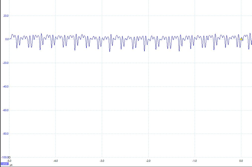
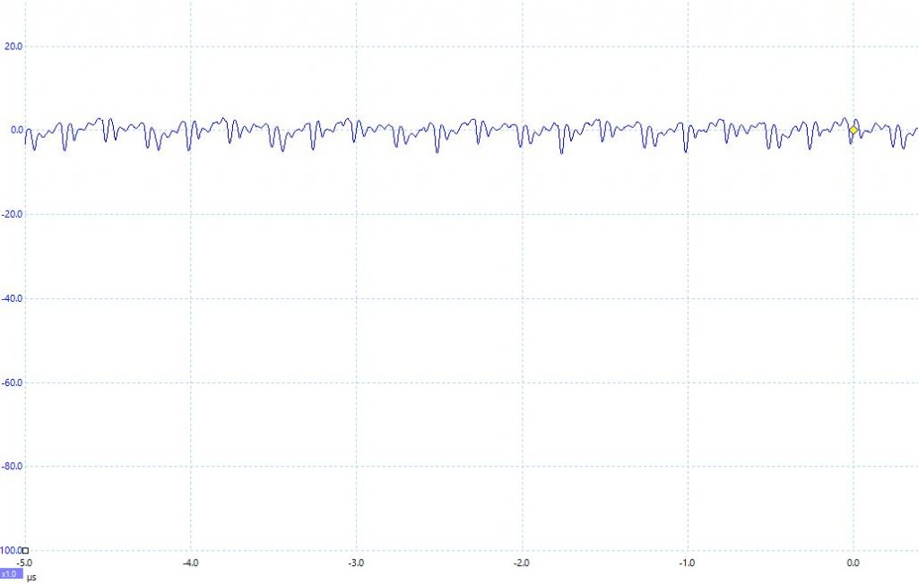
I added the pics below showing the change in the control signal noise. The first one is the "Before" which is with our own 12 VDC supply and the stock 5 VDC regulator on the board.  The second graph shows the "After" when I replaced the stock 5V switching regulator with a cheap LM7805 linear regulator and powered the board with a 12 VDC battery.

The scale on the left is in millivolts and the time scale is in microseconds so each major tic is 1 MHZ. This high frequency noise is no doubt induced by the microcontroller running at 4 MHZ effective with a 16 MHZ crystal.

There's noise that matters and then there's just noise. Arguably, this noise is so far out of the audible range as to be irrelevant. Plus in order for this to be "heard" by the audio side of the LDRs, the LDR photoresistors would have to have a comparable bandwidth which they definitely do not. The reaction time of LDRs to changes in LED current/brightness is a few millisconds and not microseconds. Said differently, the LDRs filter out this noise.


« Last Edit: 22 Jun 2015, 02:11 pm by tortugaranger »